


Page 5SKU 38437
Setting Depth Stops
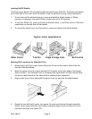
The Plate Joiner features a 3-position depth stop wheel with three notches indicating
different depths. For example, when using a #0 plate, rotate the Depth Adjusting Dial (48) to
the notch marked “0”.
1. Pull the Depth Adjusting Dial (48) out to disengage and rotate to the desired notch (0,
10, or 20). Reengage Dial.
2. Turn tool upside down and place Adjustable Front Fence (44) against a solid surface,
push forward on the tool until it stops and is held in position.
3. Check to see where the indicator lines up on the depth scale. The indicator should be
slightly past the depth number selected (0, 10, or 20).
4. If the indicator does not line up (step 3), rotate the Long Screw (46) one way or the
other until the indicator lines up on the depth scale (step 3).
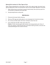
Changing Blades
Warning: To prevent personal injury, always disconnect the power to the
tool before removing or installing blades.
1. Disconnect power and turn tool upside down.
2. Loosen screws (56) in Adjustable Front Fence (44) and lower fence to expose the two
screws that hold the base assembly together.
3. Using the Hex Wrench, remove both screws from front section of Joiner (43) assembly.
4. Place the Arbor Wrench (included accessory) on spindle and hold to prevent the
spindle from rotating.
5. Place an adjustable wrench (or 24 mm wrench) on the Blade Bolt (62) and loosen
counterclockwise, removing bolt.
6. Slide Cutting Blade (61) out, noting the direction of the blade teeth.
7. Install the new Cutting Blade onto the bushing, making sure blade teeth are facing the
correct direction (see arrow on illustration, next page).
8. Replace Blade Bolt (62) and tighten clockwise until secure.
9. Reassemble Adjustable Front Fence (44) and lower fence assembly to Joiner base
assembly using the two screws.