


Page 11For technical questions, please call 1-800-444-3353.Item 69684
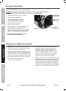
Using the Workpiece Extension Supports
1. The Table Extensions are inserted into each side of
the Table, and locked in place using the Wing Screws.
2. When properly installed, the upper face of the
Table Extensions are level with the Table, and
provide a wider support surface for the workpiece.
3. Support the workpiece to be level with the table,
and so that after the cut is made the cut off pieces
will not fall. Use sawhorses or other supports
(not included) to support longer workpieces.
4. If the workpiece is not level, you will make
an unintentional bevel cut in the material.
If the workpiece is not supported, it will bind
the blade and may cause the material to
kick back, potentially causing injury.
Adjusting the Miter Angle
A miter cut is one that is at an angle across the horizontal surface of the material. 45º miter cuts to join two pieces
in a right angle corner are common. A 30º cut is often used for a scarf joint or to make a chamfered end.
1. Loosen the Miter Knob by turning it
approximately 1/4 turn counterclockwise.
2. Press down the Miter Lock to unlock the Table.
While holding the Miter Lock down,
move the Table to the desired angle.
3. The Miter Angle Indicator will indicate the selected
angle. While the Miter Lock is released, the table will
lock into place at often used miter angles, including
22.5º, 30º, 45º, and 90º on both left and right sides.
4. Tighten the Miter Knob after adjusting the miter angle.
5. With the Table adjusted to the desired angle,
place the workpiece flush against the Fence,
secure it with the Clamp and make the cut.
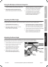
Adjusting the Bevel Angle
A bevel cut is one that is at an angle vertically. Bevel cuts can be used to miter relatively wide and
thin material. Bevel cuts can be used in combination with a miter cut to form a compound angle.
Compound angle cuts are often used in crown moldings, picture frames and similar trim materials.
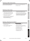
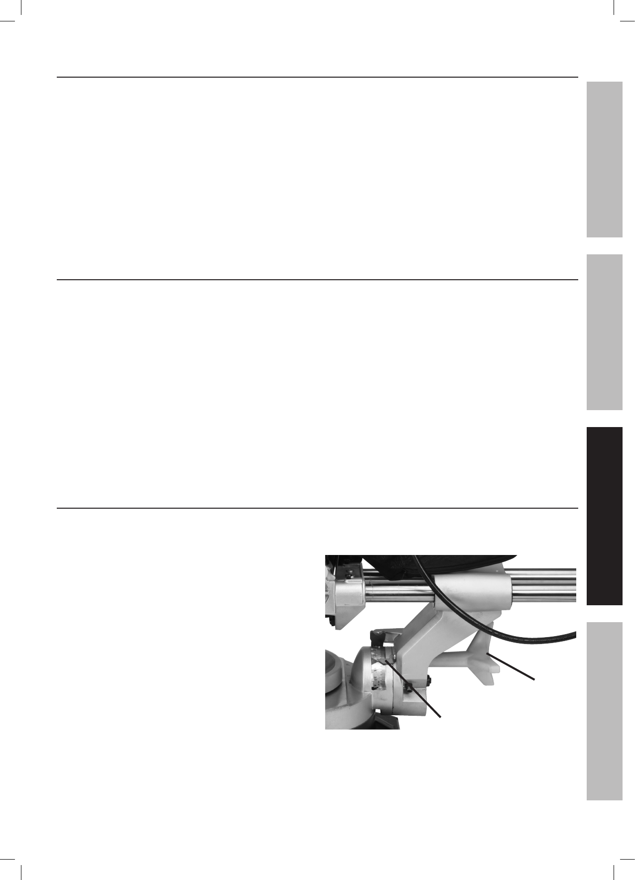
1. Loosen the Bevel Lock Knob at the rear of the saw.
2. Move the blade assembly to the desired angle.
Read the angle on the Bevel Indicator.
3. Lock the blade assembly into position by
rotating the Bevel Lock Knob clockwise.
Tighten firmly but do not over-tighten.
4. Make a sample cut in a piece of scrap to
confirm that the bevel angle is correct.
If it is not, correct the angle before cutting.
Bevel
Indicator
Bevel
Lock Knob
Figure C
SAFETYOPERATIONMAINTENANCE SETUP