Page 10 For technical questions, please call 1-800-444-3353. SKU 91938
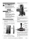
LOOSEN THE BOLT (112)7. and make
sure that the Swing Guard (53)
moves freely back into place before
operation.
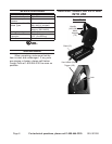
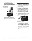
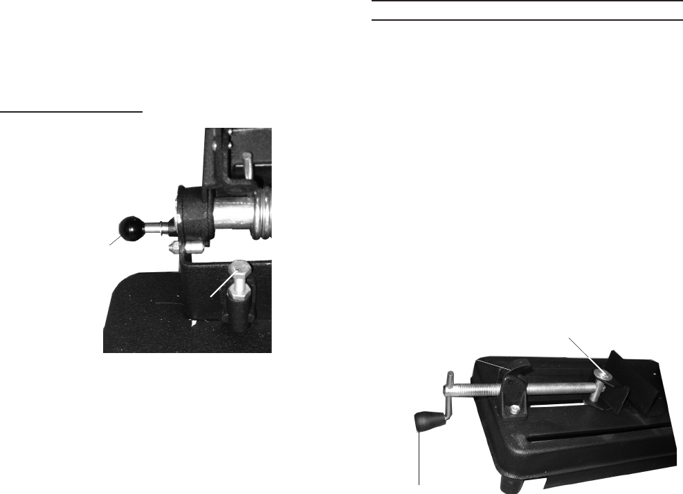
Depth Adjustment
FIGURE 3
Lock Ball (25)
Depth Adjustment
Bolt (16)
To adjust the depth, turn the Depth
Adjustment Bolt (16) shown in FIGURE
3.
Work Piece and Work Area Set Up
Designate a work area that is clean and 1.
well-lit. The work area must not allow
access by children or pets to prevent
distraction and injury.
Route the power cord along a safe 2.
route to reach the work area without
creating a tripping hazard or exposing
the power cord to possible damage. The
power cord must reach the work area
with enough extra length to allow free
movement while working.
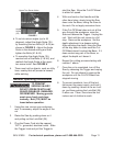
Secure loose work pieces using the vise 3.
to prevent movement while working:
FIGURE 4
Vise Handle (28)
Place Workpiece Here
Quick
Release (31)
a. To use the Quick Release (31), put the
Quick Release (31) tab in the position
shown in FIGURE 4 and push the Vise
Handle (28) up against the workpiece.
Then tighten the Vise Handle (28).
When releasing, loosen the Vise Handle
(28) a few turns, lift up the Quick
Release (31), and pull the Vise Handle
(28) open.


