


For technical questions, please call 1-800-444-3353;
Troubleshooting section at end of manual.
Page 17SKU 95424, 95629
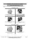
CHANGING WIRE SETTINGS
WARNING! Make sure to turn off the Welder and unplug it from its electrical
outlet prior to changing wire settings.
Lift the Door (14A) of the Welder to expose the Wire Feed Assembly.
Loosen, and lower the Handle (4D) on the Wire Feed Assembly.
Remove the Screw that secures the Roller (5D) in place. Then remove the two
Rollers.
MIG&ARC 250 AMP - SKU 95424
MIG DUAL 250 AMP – SKU
For technical questions, please call 1-800-444-3353;
Troubleshooting section at end of manual.
Page 18
TO CHANGE WIRE SETTINGS
. WARNING! Make sure to turn off the Welder and unplug it from its electrical outlet
prior to changing wire settings.
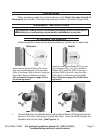
1. Lift the Door (14A) of the Welder to expose the Wire Drive Assembly.
2. Loosen, and lower the Handle (4D) on the Wire Drive Assembly.
3. Remove the Screw that secures the Roller (5D) in place. Then, remove the two Rollers.
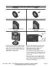
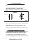
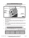
4. Flip each Roller 180 degrees. (See Figure F)
NOTE: The two Rollers are “keyed”, meaning they can only be reinstalled one way.
5. Reinstall the two Rollers, and secure the Rollers in place with the Screw. (See Figure F)
6. Install the Spool of Welding Wire, and route the Wire to the Torch Gun. Then, test and, if
necessary, adjust the Wire Drive Assembly as discussed in the previous pages of this
manual.
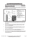
TO ATTACH THE GROUND CABLE WITH CLAMP
Insert the Connecting Plug of the Ground Cable (22A) into the Terminal Ground (7C) and
twist the Connecting Plug to lock it in place. (See Part List page 34)
.
TO ATTACH THE ELECTRODE CABLE
(Only MIG/ ARC 250 AMP)
Insert the Connecting Plug of the Electrode Cable (21A) into the Terminal Electrode (6C)
and twist the Connecting Plug to lock it in place. (See Part List page 34)
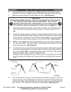
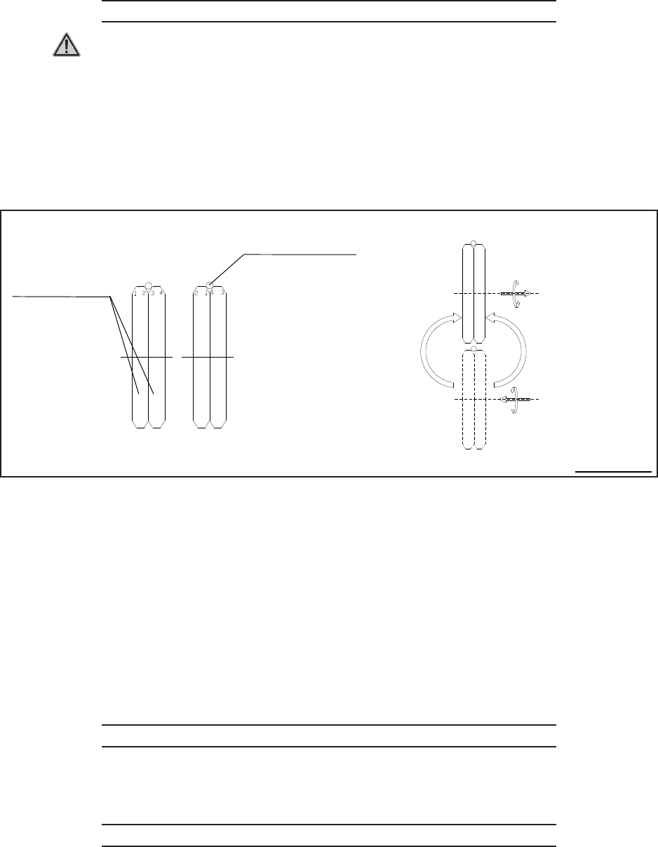
WELDING WIRE
ROLLERS
(
5
D
)
FLIP 180
°
°°
°
FIGURE F
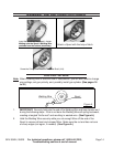
Flip each Roller 180 degrees. (See Figure F.)
Note: The two Rollers are “keyed”, which means they can only be reinstalled one
way.
Reinstall the two Rollers and secure the Rollers in place with the Screw.
(See Figure F.)
Install the Spool of Welding Wire and route the Wire to the Torch Gun. Then, test
and, if necessary, adjust the Wire Feed Assembly as discussed in the previous
pages of this manual.
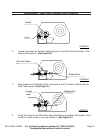
ATTACHING THE GROUND CABLE WITH CLAMP
Insert the Connecting Plug to the Ground Cable (22A) into the Terminal Ground (7C)
and twist the Connecting Plug to lock in place. (See Parts List on Page 31).
ATTACHING THE ELECTRODE CABLE (ARC WELDER ONLY)
Insert the Connecting Plug to the Ground Cable (22A) into the Terminal Electrode
(6C) and twist the Connecting Plug to lock in place. (See Parts List on Page 31).
1.
2.
3.
4.
5.
6.
7.