


Page 12SKU 96698 For technical questions, please call 1-800-444-3353.
when the Handle is lowered. Never
interfere with the proper movement of
the Blade Guard.
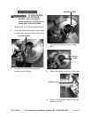
There are locking mechanisms for the 3.
miter angle and the Slides. Unlock
the Table to set the miter angle,
then re-lock it before making the
cut. Unlock the Slide using the Slide
cut if the work material is too wide to
“chop”.
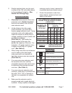
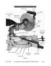
To rotate the Table to rotate it, press 4.
the Table to the desired angle,
Notches are machined into the Base
of the tool which will lock the Table
into several often used miter angles.
These angles are 0º (centered), 15º,
22.5º, 30º and 45º, both left and right
cut.
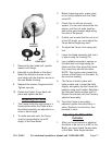
On wider pieces, you will have to 5.
slide the blade while making the cut.
To unlock the Slide, loosen the Slide
saw.
To make a bevel cut, release the 6.
assembly to the desired bevel angle,
then lock the blade assembly in place
bevel cuts is discussed in more detail
later in this manual.
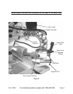
This saw is provided with a Kerf 7.
Board. The Kerf Board helps to
prevent tear-out on the bottom side
of the work material. The Kerf Board
is factory adjusted prior to shipment
of this tool so the blade does not
contact the Kerf Board during normal
operation, including bevel cuts.
Adjustment of the Kerf Board and
discussed later in this booklet.
Before starting work, check the 8.
accuracy of the Guide Fence, miter
angle and bevel angle. Instructions
for checking and adjusting these
angles are discussed later in this
booklet.
It is very important that the work 9.
material be properly supported before
making a cut. The material must be
level on the Table. The material must
be supported on both ends. Using the
Work Piece Extension Supports is
discussed in the next section.
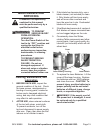
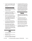
Using the Work Piece Extension
Supports
The Work Piece Extension Supports 1.
are inserted into each side of the
Table, and locked in place using the
Wing Screws.
When properly installed, the upper 2.
face of the Work Piece Extension
Supports are level with the Table, and
provide a wider support surface for
the work piece.
Always support the work piece to be 3.
level with the table, and so that after
the cut is made the cut off pieces
will not fall. You may need to use
saw horses or other supports (not
included) to support the work piece.
If the work piece is not level, you will 4.
make an unintentional bevel cut in
the material. If the work piece is not
supported, it will bind the blade and
may cause the material to kick back,
potentially causing injury.