


Page 9SKU 97750 For technical questions, please call 1-800-444-3353.
Work Piece and Work Area Set Up
Designate a work area that is clean 1.
and well-lit. The work area must not
allow access by children or pets to
prevent injury and distraction.
Route the Power Cord (34) along a 2.
safe route to reach the work area
without creating a tripping hazard
or exposing the Power Cord to pos-
sible damage. The Power Cord must
reach the work area with enough
extra length to allow free movement
while working.
Secure loose workpieces using a vise 3.
or clamps (not included) to prevent
movement while working.
There must not be hazardous ob-4.
jects, such as utility lines or foreign
objects, nearby that will present a
hazard while working.
Cover all furniture, decorations, 5.
oors, walls, etc. not intended to be
painted.
Only paint in well ventilated dust free 6.
area.
Tool Set Up
Mix and thin the paint or other uid 1.
thoroughly according to the manufac-
turer’s directions.
Carefully strain the paint/uid through 2.
a paint strainer or piece of cheese
cloth.
Fill the Cup (27) to approximately 3.
3/4 full. Then attach the Cup to the
Spray Gun. (See Figure A, on page
8.)
Plug the Power Cord (34) into the 4.
nearest 120 volt, grounded, electrical
outlet. Then turn the Power Switch
(33) to its “ON” position.
(See Figure A, on page 8.)
Adjust the air pressure during op-5.
eration with the Trigger (6) and the
Air Control Lever (13). Turn the Air
Control Lever clockwise to provide
less air to the Spray Gun. Turn the
Air Control Lever counterclockwise
to provide more air to the Spray Gun.
(See Figure A, on page 8.)
Set up a piece of scrap material to 6.
practice on. While practicing on the
scrap material, check to see that the
paint/uid you are spraying has the
appropriate consistency. If it appears
too thick, add a very small amount of
thinner (not included).
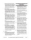
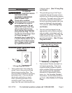
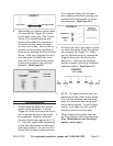
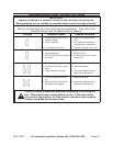
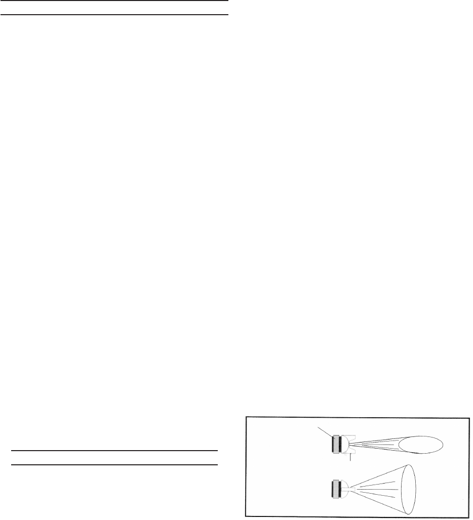
To change the direction of the fan 7.
from horizontal to vertical, loosen the
Air Cap Screw (5) and turn the Air
Nozzle (4) 90 degrees. After the ad-
justment, tighten the Air Cap Screw.
(See Figure B.)
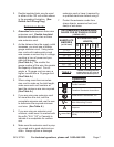
To set the pattern size specic to the 8.
job, use the Fluid Control Screw (19).
Turn it clockwise for a round pattern.
Turn the Screw counterclockwise (all
the way open) to atten the pattern.
(See Figure C, next page.)
FIGURE B
HORIZONTAL FAN
VERTICAL FAN
AIR NOZZLE (4)
AIR CAP SCREW (5)