


Installation Instructions CTA-111
6
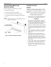
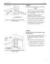
STEP 4
Attaching Bottom Stud Spanning Adapter
to Wall
1. Using a 15/64” drill bit, drill two pilot holes for
anchoring the bottom stud-spanning adapter (10) to the
wall. See Figure 5.
2. Using two 5/16” lag bolts (20) and two 5/16” flat washers
(30), attach the bottom stud-spanning adapter (10) to the
wall.
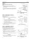
STEP 5 [REFERENCE ONLY]
Attaching Front Cover
1. Locate front cover and four M4 x 8mm Phillips head cap
screws.
NOTES
The front cover may be partially removed and
reinstalled to conceal power/audio/video cables after
the TV/Mount is installed.
You may remove one or both knockouts on cover to
assist routing to wall through cover.
2. Install the front cover using four M4 8mm Phillips head
cap screws. See Figure 6.
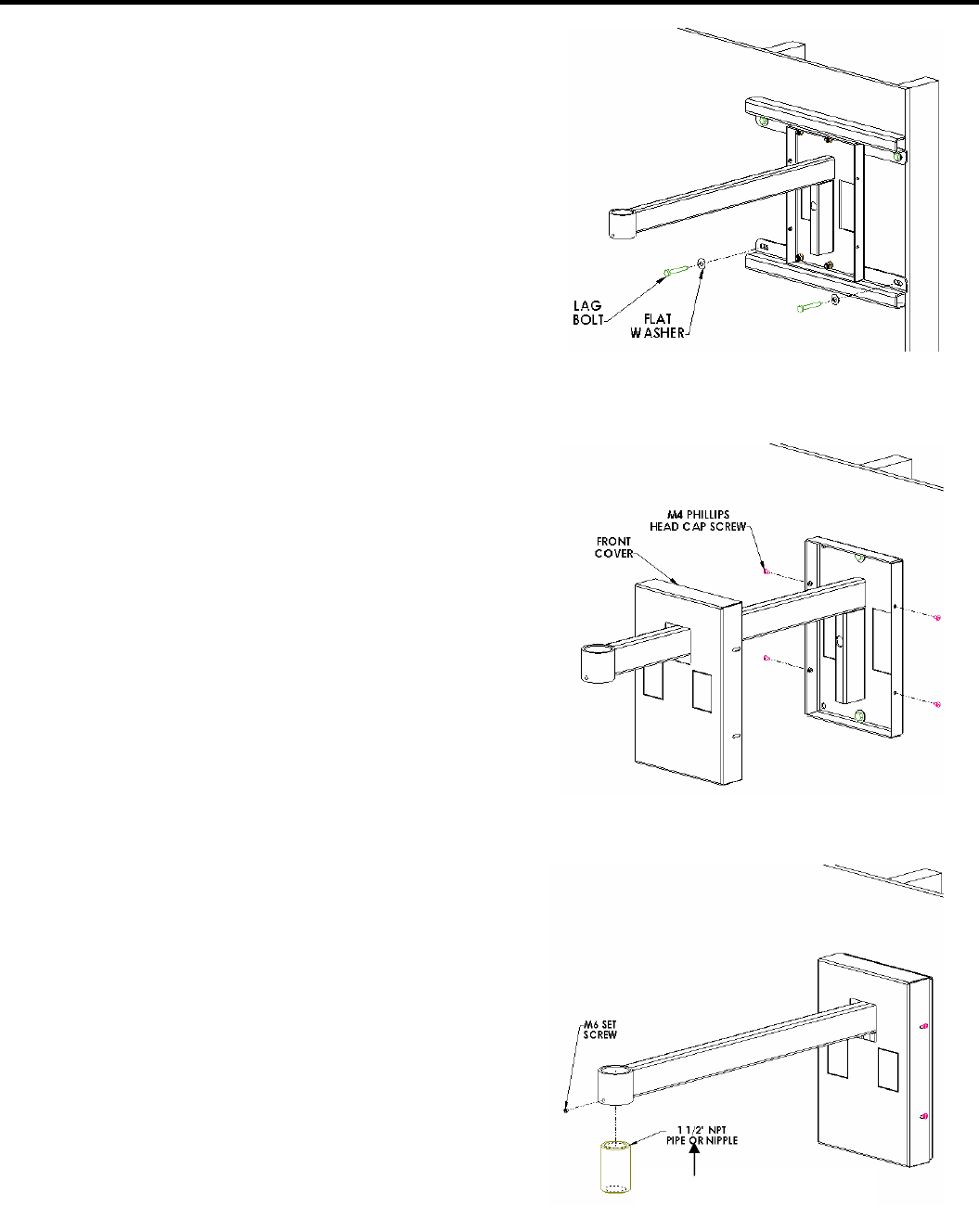
STEP 6 [REFERENCE ONLY]
Connecting NPT Pipe or Nipple to Wall Arm
1. Locate M6 x 6mm set screw and 1-1/2” NPT pipe or
nipple (supplied with TV Mount or purchased
separately).
2. Connect the 1-1/2” NPT pipe or nipple (supplied with TV
Mount or purchased separately) to the wall arm. See
Figure 7.
3. Using the M3 Allen key, install the M6 x 6mm set screw.
Tighten the set screw.
WARNING
Make sure to tighten the M6 x 6mm set screw to prevent
equipment damage or personal injury.
Figure 5. Attach Bottom Stud Spanning
Adapter to Wall
Figure 6. Attach Front Cover
Figure 7. Connect NPT Pipe or Nipple
to Wall Arm
(Supplied with
TV Mount
or purchased separately)