


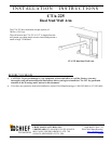


Installation Instructions CTA-225
5
TOOLS REQUIRED FOR
INSTALLATION
The tools required for installation are as follows:
• Electric drill and bit set
• Stud sensor (mechanical or electronic)
• ½” box-end wrench or ratchet with ½” socket
• 13mm box-end wrench or ratchet with 13mm socket
• Level
NOTE: Other tools may be required depending on
your method of installation.
INSTRUCTIONS
STEP 1
Installing Top Stud Spanning Adapter to Wall
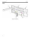
NOTE: The top and bottom stud-spanning adapters
must be mounted to wood studs that are 16”
apart on center. See Figure 2.
1. Locate the top 16” stud-spanning adapter (20), four
lag bolts (40), and four flat washers (50).
WARNING
It is the installer’s responsibility to verify that the
structure to which the mount is anchored will safely
support five times the combined load of all attached
components and equipment.
2. Determine a suitable mounting location. Keep in
mind that both stud-spanning adapters (20) must be
mounted to wood studs that are 16” apart on center.
3. Using a stud sensor, locate the two wood studs where
you will mount the top stud-spanning adapter (20).
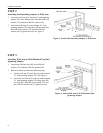
4. Holding the top stud-spanning adapter (20) against
the wall, use a pencil, awl, or small nail to mark the
mounting holes where two pilot holes will be drilled
into the center of the wood studs. Make sure that the
mounting holes in the unit are level.
5. Using a 15/64” drill bit, drill two pilot holes for
anchoring the top stud-spanning adapter (20).
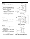
6. Using two 5/16” lag bolts (40) and two 5/16” flat
washers (50), install the top stud-spanning adapter
(20) on the wall.
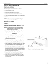
Figure 2. Install Stud Spanning Adapter
16”