


3-40
Cisco 860 Series, Cisco 880 Series, and Cisco 890 Series Integrated Services Routers Hardware Installation Guide
OL-16215-11
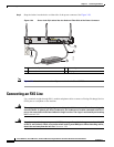
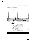
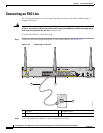
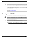
Chapter 3 Connecting the Router
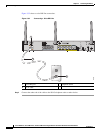
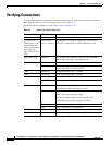
Verifying Connections
Verifying Connections
To verify that all devices are properly connected to the router, first turn on all the connected devices,
then check the LEDs. To verify router operation, refer to Table 3-3.
For the full LED descriptions, see the “LEDs” section on page 1-35.
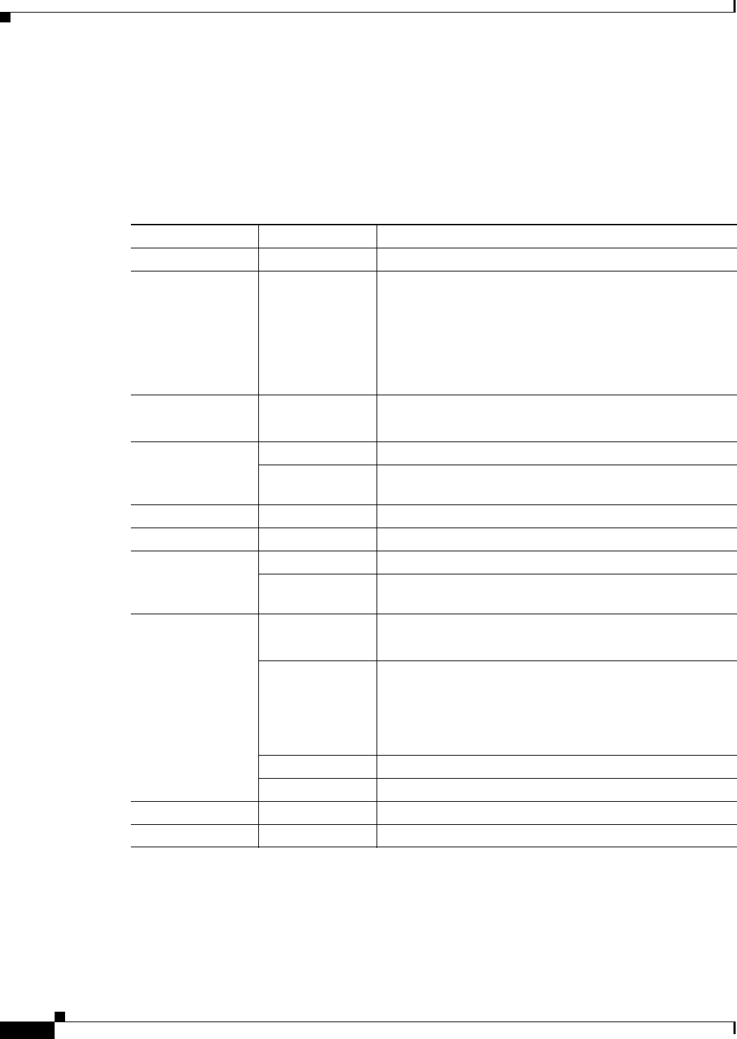
Table 3-3 Verifying the Router Operation
Power and Link LEDs to Check Normal Patterns
Power OK On when power is supplied to the router.
To servers, PCs,
workstations, or an
external Ethernet
switch connected to
the LAN ports
(FE0
1
, FE1, FE2, or
FE3)
LAN 0, LAN 1,
LAN 2, or LAN 3
On when the FE LAN port is physically connected to a
server, PC, workstation, or external Ethernet switch.
To FE WAN line WAN FE4 On when the WAN Ethernet carrier has detected status.
Blinks when receiving or transmitting data.
To xDSL
2
line xDSL CD Green when the line is connected to the xDSL DSLAM
3
.
xDSL Data Green when receiving or sending data.
Blinks when line is in training mode.
ATM 898EA only Green when ATM mode is selected.
EFM 898EA only Green when EFM mode is selected.
To ISDN line Data BRI LNK Green when the ISDN line is connected.
Data BRI B1 and
B2
Green when the channel is connected.
3G
4
WWAN
5
Green when service is established.
Slow blinking when searching for service.
RSSI
6
Amber when service is not established.
Green when signal strength is high.
Off or slow blinking when signal strength is low.
Fast blinking when signal strength is medium.
CDMA
7
Green when service is established.
GSM
8
Green when service is established.
To PPP
9
clients PPP Green when either a PPPoE
10
or PPPoA
11
client is running.
To VPN
12
tunnel VPN Green when a crypto session is running.