


2-12
Cisco 860 Series, Cisco 880 Series, and Cisco 890 Series Integrated Services Routers Hardware Installation Guide
OL-16215-11
Chapter 2 Installing the Router
Installing the Router
Caution Chassis installation must allow unrestricted airflow for chassis cooling.
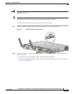
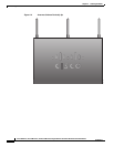
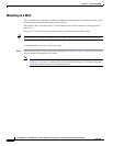
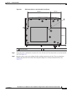
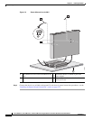
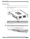
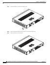
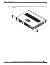
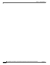
Step 3 Using two screws for each side (supplied with the rack), attach the Cisco 890 series ISR with rack-mount
brackets to a 19-inch rack. Start with the lower pair of screws first, resting the brackets on the lower
screws while you insert the upper pair of screws.
Note Be sure to leave space above and below each unit in a rack to allow for cooling air circulation.
Note Do not stack equipment directly above the router. Keep at least 1 rack unit of space above the
router.
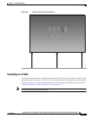
Tip The screw slots in the brackets are spaced to line up with every second pair of screw holes in the
rack. When the correct screw holes are used, the small threaded holes in the brackets line up with
unused screw holes in the rack. If the small holes do not line up with the rack holes, you must
raise or lower the brackets to the next rack hole.
Step 4 Place the power adapter on a nearby horizontal surface.
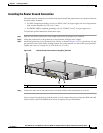
Step 5 Connect the chassis to a reliable earth ground. For the chassis ground connection procedures, see the
“Installing the Router Ground Connection” section on page 2-13.
Warning
To prevent bodily injury when mounting or servicing this unit in a rack, you must take special
precautions to ensure that the system remains stable. The following guidelines are provided to
ensure your safety:
• This unit should be mounted at the bottom of the rack if it is the only unit in the rack.
• When mounting this unit in a partially filled rack, load the rack from the bottom to the top with the heaviest
component at the bottom of the rack.
• If the rack is provided with stabilizing devices, install the stabilizers before mounting or servicing the unit in
the rack.
Statement 1006