


OPERATING
INSTRUCTIONS
AND
PARTS LIST
FOR
DRILL PRESS
MODEL
NUMBER
103.24521
AND
103.24531
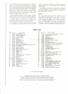
HEADSTOCK
LOCK
HANDLE
FEED
RETURN
SPRING
ADJ.
KNOB
FEED
RETURN
SPRING
ADJ.
KNOB
LOCK
SCREW
TABLE
LOCK
HANDLE
LOCK
HANDLE
BENCH
MODEL
MOTOR
MOUNT
CHUCK
MOTOR
MOUNT
LOCK
SCREW
FEED
STOP
FEED
STOP
ROD
FEED
HANDLE
CHUCK
KEY
FLOOR
MODEL
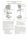
FIGURE
1
This
drill press
has
been planned
to
give
you the
utmost
in
precision
and
efficiency
of
operation.
Quality material coupled with rigid
manufacturing
standards
are
maintained
to
give
you the
high stand-
ard of
quality
found
in
this tool.
The
chuck
furnished
has a
collar attached which
will
keep
it firmly
seated
on the
spindle taper
for all
operations especially
where side thrust
on the
cutting tool, such
as
routing,
might
loosen
the
chuck.
Exterior
styling
of the
head
on
this
drill
press
encloses
the
revolving mechanism
for
safety,
yet
leaves
the
belt readily accessible
for
changing
to
obtain
different
spindle
speeds.
All
features
combine
to
give
you
maximum trouble
free
service.
To
prevent damage
or
loss
in
shipment some
of
the
parts
were
disassembled
from
the
tool.
These
parts
are
listed below.
Be
sure they
are all
accounted
for
before discarding
any of the
packing materials.
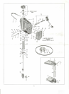
Box
located under table contains:
1.
Item
No. 64,
Column plug.
2.
Item
No.
59,
V-belt.A-
3.
Item
No. 28,
Chuck
key."''
4.
Item
No. 60,
Motor pulley
with
set
screw.
5.
Item
No.
27,
Chuck,
l^
6.
Three
assemblies, each
consistingj>f
Item
No. 53,
Feed handle rod.
Item
No. 52,
Feed
handle
7.
Items
No. 41, 42 and 44,
Bumper
and
Stud
Assembly.
8.
Paper
bag
contains:
Item
No. 1 4,
Allen
wrench
3/32.
Item
No. 62,
Allen wrench 5/32.
Item
No. 44, 4
pcs. Motor bolt nuts.
Item
No. 48, 8
pcs. Motor bolt washers.
^
Item
No. 49, 4
pcs. Motor bolts
*•
Items
No. 34, 35, 36 and 37
assembled.
ASSEMBLY:
Place
feed
handles
on
tool
as
shown
in
Fig.
1.
Clean taper
on
spindle
and the
tapered socket
in
chuck
body.
Be
sure they
are
free
of any
particles
which
might
not
allow proper seating. Apply
a
film
of
light
oil to
both
spindle
taper
and
chuck
socket. Place chuck
on end of
spindle
and
screw
the
collar onto
the
threaded portion
of the
spindle.
Tap the
chuck body,
not
jaws,
from
below with
a
piece
of
wood
to firmly
seat
it on
spindle, then
tighten collar.
The
collar does
not
need
to be ex-
cessively tight
as it has a
tendency
to
tighten when
drill
press
is
running.
Place
the
chuck
key in the
hole provided
at
side
of
table support,
see
Fig.
1.
Keep
the
Allen wrenches
in a
handy place near
the
tool.