


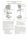
INSTALLATION:
Three
1
3/32 inch diameter holes
have
been
pro-
vided
in the
base
through which bolts
or
screws
may
be
inserted
to
secure
the
drill
press
to a
well con-
structed bench
or
tool
stand.
To
install motor loosen
the
motor mount
lock
screws, Fig.
1,
until
the
motor mount
may be re-
moved.
Fasten
the
motor
to the
motor mount with
the
bolts, nuts,
and
washers provided
so
that when
motor mount
is
reinstalled
on the
tool,
the
larger
portion
of the
mount will
be
down.
For
convenience,
if
your motor
has a
switch,
and
rotation
will
be
cor-
rect, place motor
on
motor mount
so
that
the
switch
is
on the
left
side. Direction
of
rotation
of the
spindle must
be
clockwise when viewed from pulley
end of
spindle.
Mount
the
motor pulley,
No. 60, on
motor
shaft
so
that
the
small diameter
is at
bottom.
For
normal
speeds,
the
largest groove
on the
motor pulley should
be in
line with
the
smallest
groove
on the
spindle
pulley,
No.
1.
Tighten
the
pulley
set
screw with
the
larger Allen
wrench,
No. 62. If
your motor
shaft
has a flat on
it,
position
the
pulley
so
that
the set
screw will
tighten
against
the flat.
Place
belt around
the
pulleys
and
tighten,
not
excessively,
by
sliding
the
motor mount away
from
tool.
Tighten
the
motor mount lock screws
to
maintain
this tension.
Adjust
the
screw,
No. 42,
until
the
center line
of
the
motor
is
parallel with
the
center line
of the
column.
MOTOR:
A
4/£
horsepowei^475Q
R.P.M^baH
bearing
mutor
will
provide
sufficient
speed
and
power
for
your
drill
press
on
general work.
For
continuous heavy
duty operation
a 1
/2
horsepower motor
is
recom-
mended.
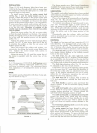
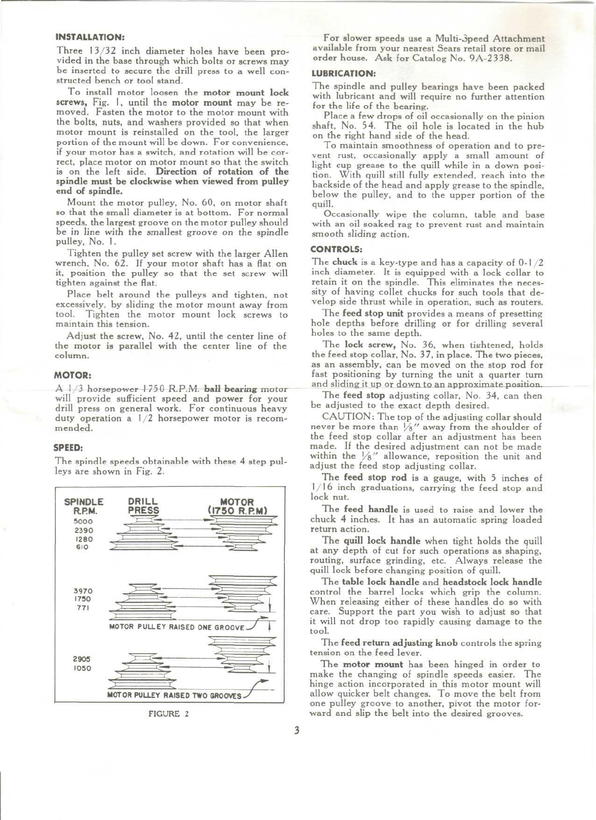
SPEED:
The
spindle speeds obtainable with these
4
step pul-
leys
are
shown
in
Fig.
2.
SPINDLE
R.P.M.
5000
2390
1280
610
3970
1730
771
DRILL
PRESS
MOTOR
(1750
R.P.M)
I
MOTOR
PULLEY
RAISED
ONE
GROOVE-/
|
2905
1050
MOTOR
PULLEY
RAISED
TWO
GROOVES-'
FIGURE
2
For
slower speeds
use a
Multi-Speed
Attachment
available
from
your nearest Sears retail store
or
mail
order house.
Ask for
Catalog
No.
9A-2338.
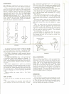
LUBRICATION:
The
spindle
and
pulley bearings have been packed
with
lubricant
and
will require
no
further
attention
for
the
life
of the
bearing.
Place
a few
drops
of oil
occasionally
on the
pinion
shaft,
No. 54. The oil
hole
is
located
in the hub
on
trie
right hand side
of the
head.
To
maintain smoothness
of
operation
and to
pre-
vent
rust,
occasionally apply
a
small amount
of
light
cup
grease
to the
quill
while
in a
down posi-
tion.
With
quill
still
fully
extended, reach into
the
backside
of the
head
and
apply grease
to the
spindle,
below
the
pulley,
and to the
upper portion
of the
quill.
Occasionally
wipe
the
column,
table
and
base
with
an oil
soaked
rag to
prevent rust
and
maintain
smooth
sliding action.
CONTROLS:
The
chuck
is a
key-type
and has a
capacity
of
0-1
/ 2
inch
diameter.
It is
equipped with
a
lock collar
to
retain
it on the
spindle. This eliminates
the
neces-
sity
of
having collet chucks
for
such tools that
de-
velop side thrust while
in
operation, such
as
routers.
The
feed stop
unit
provides
a
means
of
presetting
hole depths before drilling
or for
drilling several
holes
to the
same depth.
The
lock screw,
No. 36,
when
tightened,
holds
the
feed
stop collar,
No.
37,
in
place.
The two
pieces,
as an
assembly,
can be
moved
on the
stop
rod for
fast
positioning
by
turning
the
unit
a
quarter turn
and
sliding
it up or
down
to an
approximate
pr.aifir.ri,
The
feed
stop
adjusting
collar,
No. 34, can
then
be
adjusted
to the
exact depth desired.
CAUTION:
The top of the
adjusting collar should
never
be
more than
J/s"
away
from
the
shoulder
of
the
feed
stop collar
after
an
adjustment
has
been
made.
If the
desired
adjustment
can not be
made
within
the
J/g"
allowance, reposition
the
unit
and
adjust
the
feed
stop
adjusting
collar.
The
feed stop
rod is a
gauge, with
5
inches
of
1/16
inch graduations, carrying
the
feed
stop
and
lock nut.
The
feed handle
is
used
to
raise
and
lower
the
chuck
4
inches.
It has an
automatic spring loaded
return
action.
The
quill lock handle when tight holds
the
quill
at any
depth
of cut for
such operations
as
shaping,
routing,
surface
grinding, etc. Always release
the
quill
lock before changing position
of
quill.
The
table
lock handle
and
headstock lock handle
control
the
barrel locks which grip
the
column.
When releasing either
of
these handles
do so
with
care.
Support
the
part
you
wish
to
adjust
so
that
it
will
not
drop
too
rapidly causing damage
to the
tool.
The
feed return adjusting knob controls
the
spring
tension
on the
feed
lever.
The
motor
mount
has
been hinged
in
order
to
make
the
changing
of
spindle
speeds
easier.
The
hinge
action incorporated
in
this motor mount
will
allow quicker belt changes.
To
move
the
belt
from
one
pulley groove
to
another, pivot
the
motor for-
ward
and
slip
the
belt into
the
desired
grooves.