


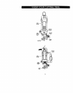
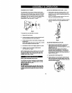
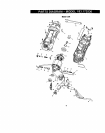


CHANGINGCOLLETINSERT
Thecutting bits forthis tool are locked into place with a
collar nut (1) and coJlet(see Fig. 3). The tool is assembled
at the factory with NO coilet installed. Both the l/a"and ¼"
coilets can be found inthe carrying case front lidstorage
compartment. The 1/8"toilet (2) is used forholding hobby
tool accessory bits. The ¼" coflet (3) is supplied for
holding SMALL router bits with a %"shank.
Fig. 3
To change from one cotlet size to the other:.
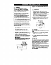
1. Remove bit from the tool.
2. Continue turning the collet nut counter clockwise until
it can be removed from the motor shaft (4).
3. Pull the co,el out of the motor shaft and replace itwith
the other one.
NOTE: Each colletis the same on both ends, so either
end can be inserted into the motor shaft,
4. Re-install the collet nut and slightlytighten it by hand.
5. Install the new bitas outlined inINSTALLING
CUTTING BITS on Page 9.
NOTE: Tightaning the oollet nut without a bitin the sallet
will cause the collet hole to become smaller and make
installing bitsdifficult. When stodng the tootwith no bit
installed, leave collet nut loose.
j _'4::1:1:r_,l_A0]l,-,]la]iP_s-_J_,__-_._
INSTALLING FREEHAND SOLE PLATE
The freehand sole plate is designed for basic freehand
cuffing with the cuffing bit. It is ideally suited for cuffing
electrical outlet holes in dPJwall.
IA WARNING I
Do NOTuse the freehand sole platewith routerbits.
Limitedcontrolwith this accmmorycould cause you
to lOOSecontrol and Increasethe chance ofserious
Injury,
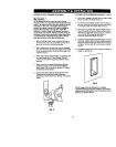
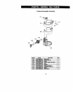
INSTALLING FREEHAND SOLE PLATE - €ont'd
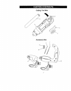
1. Slide freehand sole plate mounting bracket (1) onto
the bottom of motor housing (2) untilthe slot inthe
bracket (3) lines up with the shaft lockingbutton (4) in
the motor housing.
NOTE: The mounting bracket must be pushed onto
the motor housing as far as it will go.
2. Lock the sole plate tothe motor housing bysnapping
the quick locking lever (5) firmly againstthe motor
housing.
2
4
3
5
Fig. 4
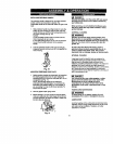
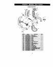
ADJUSTING FREEHAND SOLE PLATE
1.
2.
3.
Adjust freehand sole plate depth bylooseningthe
depth gauge locking knob (6) and rotating the
adjusting knob (7) tomove the soleplate in or out as
required (see Rg. 5).
NOTE: Set the depth gauge so the cuttingbit
protrudes beyond the sole plate 1/0"more than the
thickness of the matadal being cut. For example, if
you are cutting s/6"drywall, the bit shouldprotrude ¾"
beyond the sole plate.
Securely tighten depth gauge knob.
Before starting to cut you should re-check bitdepth.
Make sure sole plate isat dght angles to the bitand
securely tightened. Re-check the collarto make sure
the bit is sacureb/fastened.
lO
Fig. 5