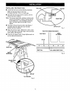
• Insert the two remaining pan head screws into
holes in the fine adjustment knob bracket.
• Attach the fine adjustment knob bracket to the
bottom of the fence head on the right or the left
side of the fence handle. Securely tighten the two
screws.
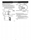
BRACKET
SCREWS _ _
Fig. 9
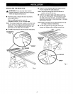
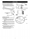
MOUNTING THE SWITCH
• Locate the switch assembly, The fasteners should
still be attached.
Note: If the fasteners were removed from the switch,
see instructions in your table saw Owner's
Manual for mounting the switch or refer to
Figure 10.
• Holding the switch to the front, insert and slide the
two square nuts into the lower slot of the front rail.
_I, WARNING: Place the switch out of the immedi-
ate work area to avoid accidentally turning it off
during operation.
• Slide the switch assembly to a convenient position,
leaving ample clearance for the handwheel.
Tighten securely with a screwdriver.
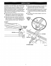
• Attach the front rail end caps and screws with a
phillips screw driver. See Figure 11.
FRONTRAIL
SWITCH
ASSEMBLY
P
\
TABLE
EXTENSION
SWITCHSCREW
Fig. 10
ENDCAP
SCREW
Fig. 11


