


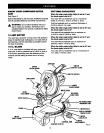
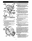
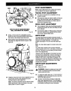

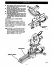

TABLE
COMBINATION
SQUARE
BLADE
VIEWOF BLADENOTSQUAREWITHMITER
TABLE,ADJUSTMENTSAREREQUIRED
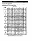
Fig. 23
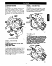
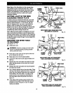
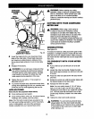
Using a 10 mm wrench or adjustable wrench,
loosen the lock nut securing positive stop adjust-
ment screw. Also loosen bevel lock knob.
Adjust positive stop adjustment screw to bring
saw blade into alignment with the square. See
Figure 24.
POSITIVESTOP
ADJUSTMENT
SCRE• FOR
4S° ANGLES
Fig. 24
Retighten bevel lock knob. Next, retighten lock nut
securing the positive stop adjustment screw.
Recheck blade-to-table alignment.
Note: The above procedure can be used to check
blade squareness of the saw blade to the miter
table at beth 0° and 45 ° angles.
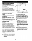
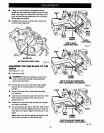
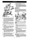
PIVOT ADJUSTMENTS
Note: These adjustments were made at the factory
and normally do not require readjustment.
TRAVEL PIVOT ADJUSTMENT
• The saw arm should rise completely to the up
position by itself.
If the sew arm does not raise by itself or ifthere is
play in the pivot joints, have sew repaired by a
qualified service technician at a Sears store to
avoid risk of personal injury.
BEVEL PIVOT ADJUSTMENT
BI Your compound miter saw should bevel easily by
loosening the bevel lock knob and tilting the sew
arm to the left.
• If movement is tight or if there is play in the pivot,
have saw repaired by a qualified service techni-
cian at your nearest Sears store.
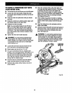
DEPTH STOP
The depth stop limits the blade's downward travel. It
allows the blade to go below the miter table enough to
maintain full cutting capacities. The depth stop
positions the blade 1/4 in. from the miter table sup-
port.
Note" The miter table support is located inside miter
table.
The depth stop is factory set to provide maximum
cutting capacity for the 10 in. saw blade provided with
your saw. Therefore, the saw blade provided should
never need adjustments.
However, when the diameter of the blade has been
reduced due to sharpening, it may be necessary to
adjust the depth stop to provide maximum cutting
capacity. Also, when a new blade is installed, it is
necessary to check the clearance of the blade to the
miter table support before starting the saw. Make
adjustments if needed.
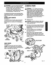
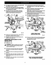
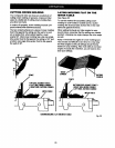
DEPTH STOP ADJUSTMENTS
See Figure 25.
• Unplug your saw.
A WARNING: Failure to unplug your saw could
result in accidental starting causing possible
serious personal injury.
BI To adjust the depth stop use a 17 mm wrench or
adjustable wrench and loosen the hex nut at the
rear of the miter saw arm.
Use the 5 mm hex key provided to adjust the
depth stop adjustment screw. The saw blade is
lowered by turning the screw counter-clockwise
and raised by turning the screw clockwise.
18