


• Turn machine off if it jams.
• Support workpiece with work table.
CAUTION: Think safety! Safety is a combination of operator
common sense and alertness at all times when tool is being
used.
WARNING: Do not attempt to operate tool until it is com-
pletely assembled according to the instructions.
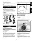
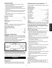
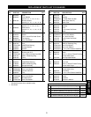
UNPACKING
Refer to Figure 1.
Check for shipping damage. If damage has occurred, a claim
must be filled with carrier. Check for completeness.
Immediately report missing parts to dealer.
The sander comes assembled as one unit. Additional parts
should be located and accounted for before assembling.
A Table Inserts (6), (½″, ¾″, 1″, 1½″, 2″ and 3″)
B Spindle Knob
C Drum Washers (5), (¾″, 1″, 1½″, 2″ and 3″)
D Spindle Drums (5), (¾″, 1″, 1½″, 2″ and 3″)
E Abrasive Sleeves (6), (
½″, ¾″, 1″, 1½″, 2″ and 3″)
ASSEMBLY
Refer to Figures 2 - 5.
CAUTION: Do not attempt assembly if parts are missing.
Use this manual to order replacement parts.
WARNING: Do not operate machine until completely assem-
bled. Do not operate machine until you have completely read
and understood this manual.
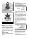
MOUNT SANDER
Refer to Figure 2.
Choose a suitable location to mount the sander. The sander
must be installed in a place with ample lighting and correct
power supply. To install sander:
• The sander must be bolted to a firm, level surface.
• Make sure there is plenty of room for moving the work-
piece. There must be enough room that neither operators
nor bystanders will have to stand in line with the wood
while using the tool.
• Sander can be installed on a workbench or a tool stand
(see Recommended Accessories, page 9) using bolts, lock
washers and hex nuts.
• Figure 2 shows the base dimensions and mounting holes.
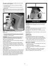
ATTACH ABRASIVE SLEEVES
Refer to Figures 3 and 4, pages 3 and 4.
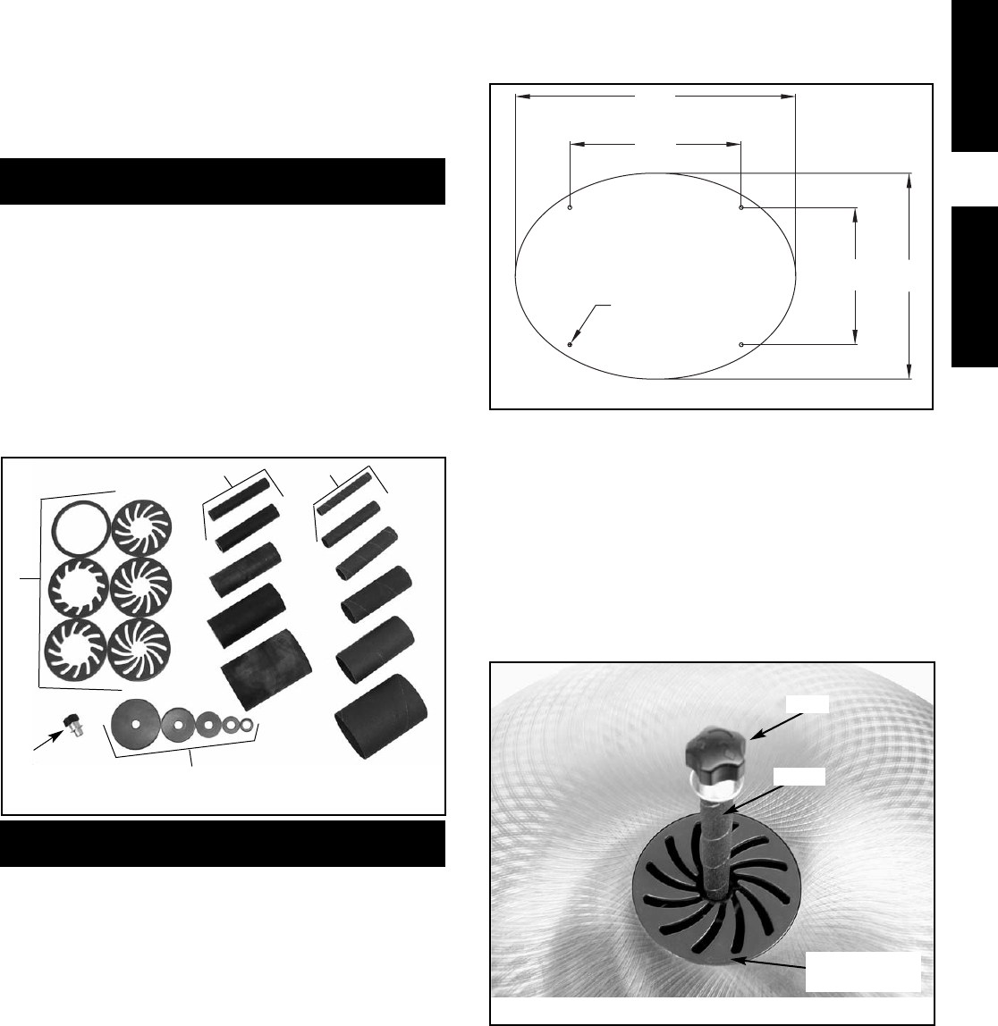
TO ATTACH ½″ ABRASIVE SLEEVE:
• Place the ½″ table insert over spindle and onto the table.
The top side of the insert has directional arrows stamped
into the insert.
• Slide sleeve over the spindle.
• Secure sleeve in position with knob.
NOTE: Knob has left hand thread – turn counterclockwise
to tighten, clockwise to loosen. Knob must seat on sleeve
securely so that sleeve will not spin loose on spindle.
TO ATTACH ¾″ – 3″ ABRASIVE SLEEVES:
Example: 2″
• Place the 2″ table insert over spindle and onto the table.
The top side of the insert has directional arrows stamped
into the insert.
• Slide 2″ sleeve over the 2″ drum.
• Slide drum with sleeve onto spindle. Place 2″ drum washer
on drum and secure drum in position with knob. Knob and
washer must hold drum firmly so that it does not spin loose
on spindle.
3
Figure 1 - Unpacking Sander
A
B
E
C
D
Figure 3 - Attaching the ½″ Sleeve
Knob
SAFETY ASSEMBLY
Figure 2 - Base Dimension and Mounting Holes
Sleeve
Direction Arrow
on Insert
22½″
16½″
13¾″
11″
5
/
16
″ Diameter