


EXTENSION CORDS
• The use of any extension cord will cause some drop in
voltage and loss of power.
• Wires of the extension cord must be of sufficient size to
carry the current and maintain adequate voltage.
• Use the table to determine the minimum wire size (A.W.G.)
extension cord.
• Use only 3-wire extension cords having 3-prong grounding
type plugs and 3-pole receptacles which accept the tool
plug.
• If the extension cord is worn, cut, or damaged in any way,
replace it immediately.
Extension Cord Length
Wire Size . . . . . . . . . . . . . . . . . . . . . . . . . . . . . . . . . . . A.W.G.
Up to 25 ft. . . . . . . . . . . . . . . . . . . . . . . . . . . . . . . . . . . . . . . 18
25 to 50 ft. . . . . . . . . . . . . . . . . . . . . . . . . . . . . . . . . . . . . . . 16
NOTE: Using extension cords over 50 ft. long is not
recommended.
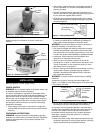
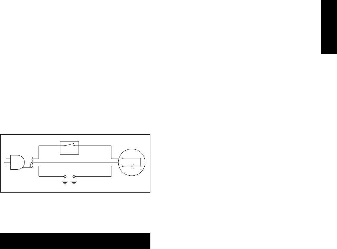
MOTOR
The sander is assembled with motor and wiring installed. The
electrical wiring schematic is shown in Figure 8.
MOTOR SPECIFICATIONS:
Horsepower (Continuous Duty). . . . . . . . . . . . . . . . . . . . . . .
1
/4
Voltage . . . . . . . . . . . . . . . . . . . . . . . . . . . . . . . . . . . . . . . . 120
Amp. . . . . . . . . . . . . . . . . . . . . . . . . . . . . . . . . . . . . . . . . . . 2.6
Hertz . . . . . . . . . . . . . . . . . . . . . . . . . . . . . . . . . . . . . . . . . . 60
Phase. . . . . . . . . . . . . . . . . . . . . . . . . . . . . . . . . . . . . . . Single
RPM. . . . . . . . . . . . . . . . . . . . . . . . . . . . . . . . . . . . . . . . . 1725
ELECTRICAL CONNECTIONS
WARNING:
All electrical connections must be performed by
a qualified electrician. Make sure tool is off and disconnected
from power source while motor is mounted, connected, recon-
nected or anytime wiring is inspected.
Motor and wires are installed as shown in wiring schematic
(See Figure 8). Motor is assembled with approved,
3-conductor cord to be used at 120 volts.
The power lines are inserted directly onto the switch. The
green ground line must remain securely fastened to the frame
to properly protect against electrical shock. The power supply
to the motor is controlled by a single pole locking rocker switch.
• Remove the key to prevent unauthorized use.
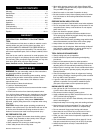
OPERATION
Refer to Figures 9 and 10.
DESCRIPTION
The Craftsman Oscillating Spindle Sander makes sanding
irregular shapes and curves in wood easy and convenient.
Sander features a large 18″ cast iron table, dust port and
onboard storage of durms, inserts and washers.
Six sizes of drums are included. Dust port is sized to fit Sears
wet/dry vacuums.
SPECIFICATIONS
Spindle diameter . . . . . . . . . . . . . . . . . . . . . . . . . . . . . . . . . ½″
Drum diameters. . . . . . . . . . . . . . . . . . . ¾″, 1″, 1½″, 2″ and 3″
Drum length. . . . . . . . . . . . . . . . . . . . . . . . . . . . . . . . . . . . 4½″
Spindle stroke. . . . . . . . . . . . . . . . . . . . . . . . . . . . . . . . . . . . 1″
Spindle oscillation . . . . . . . . . . . . . . . . . . . . . . . . . . . . 30 SPM
Spindle speed . . . . . . . . . . . . . . . . . . . . . . . . . . . . . 1725 RPM
Table diameter . . . . . . . . . . . . . . . . . . . . . . . . . . . . . . . . . . 18″
Table height . . . . . . . . . . . . . . . . . . . . . . . . . . . . . . . . . . . 14½″
Dust port diameter. . . . . . . . . . . . . . . . . . . . . . . . . . . . . 2.086″
Base dimensions . . . . . . . . . . . . . . . . . . . . . . . . . 22½ x 16½″
Switch . . . . . . . . . . . . . . . . . . . . . . . . . . . . . SP, Locking rocker
Weight . . . . . . . . . . . . . . . . . . . . . . . . . . . . . . . . . . . . . . 52 lbs
WARNING: Operation of any power tool can result in foreign
objects being thrown into the eyes, which can result in severe
eye damage. Always wear safety goggles complying with
United States ANSI Z87.1 (shown on package) before com-
mencing power tool operation. Safety goggles are available at
Sears retail stores or catalog.
CAUTION: Always observe following safety precautions.
SAFETY PRECAUTIONS
• Whenever adjusting or replacing any parts on the tool, turn
switch OFF and remove the plug from power source.
• Make sure all guards are properly attached. All guards
should be securely fastened.
• Make sure all moving parts are free and clear of any
interference.
• Make sure all fasteners are tight and have not vibrated loose.
• With power disconnected, test operation by hand for clear-
ance and adjust if necessary.
• Always wear eye protection or face shield.
• After turning switch on, always allow drum to come up to
full speed before sanding.
• Be sure drum turns clockwise.
• Avoid kickback by sanding in accordance with the direction-
al arrows.
• Keep your hands clear of abrasive sleeve and drum.
• For optimum performance, do not stall motor or reduce
speed. Do not force the work into the abrasive.
• Always support workpiece with table.
• Never push a sharp corner of the workpiece rapidly against
sleeve. Abrasive backing may tear.
• Replace abrasives when they become loaded (glazed) or
frayed.
• Never use machine for wet sanding which can create
hazard of electrical shock.
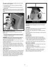
ON/OFF SWITCH
Refer to Figure 9, page 6.
The ON/OFF switch is located on the upper front right of the
base. To turn the sander ON, pull the switch to the up
position. To turn the sander OFF, push the switch to the down
position.
5
Figure 8 - Wiring Schematic
Switch
Line Cord
Motor
OPERATION