


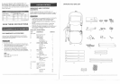
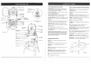
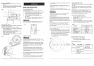
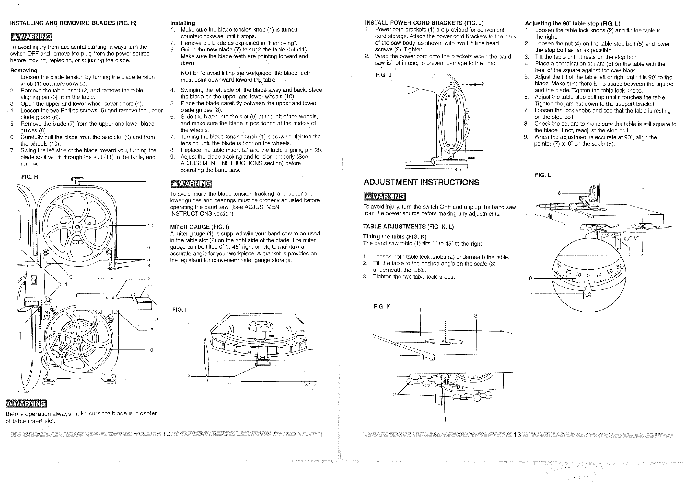
INSTALLING AND REMOVING BLADES (FIG. H)
To avoid injury from accidental starting, always turn the
switch OFF and remove the plug from the power source
before moving, replacing, or adjusting the blade.
Removing
1. Loosen the blade tension by turning the blade tension
knob (1) counterclockwise.
2. Remove the table insert (2) and remove the table
aligning pin (3) from the table.
3. Open the upper and lower wheel cover doors (4).
4. Loosen the two Phillips screws (5) and remove the upper
blade guard (6).
5. Remove the blade (7) from the upper and lower blade
guides (8).
6. Carefully pull the blade from the side slot (9) and from
the wheels (10).
7. Swing the left side of the blade toward you, turning the
blade so itwilt fit through the slot (11) in the table, and
remove.
FIG. H
10
6
5
3
2
1
Installing
1. Make sure the blade tensior knob (1) is turned
counterclockwise until it stops.
2. Remove o_eblade as explained in "Removing"
3. Guide the new blade (7) through the table slot (11).
Make sure the blade teeth are pointing forward and
down.
NOTE: To avoid lifting the workpiece, lhe blade teeth
must point aownwara toward the table.
4. Swinging the left side off the blade away and back. place
the blade on the upper and lower wheels (10).
5. Place the blade carefully between the upper and lower
blade gulaes (8).
6. Slide the blade into the slot (9) at the left of the wheels•
and maKe sure the blade is positioned at the rniddle of
the wheels.
7. Turning the blade tension knob (1) clockwise, tighten the
tension until the blade is tignt on the wheels.
8. Replace the table insert (2) and the table aligning a_n(3).
9. Adjust the utade tracking and tension properly (See
ADJUSTMENT INSTRUCTIONS sectlont before
operating the band saw.
To avoid injury, the blade tension, tracking, and upper ana
lower guides and bearings must be properly adjusted before
operating the band saw. (See ADJUSTMENT
INSTRUCTIONS section)
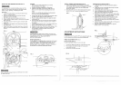
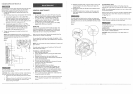
MITER GAUGE (FIG. I)
A miter gauge (1) is supplied with your band saw to be used
in the table slot (2) on the right side of the blade. The miter
gauge can be tilted 0° to 45° right or left, to maintain an
accurate angle for your workpiece. A bracket is provided on
the leg stand for convenient miter gauge storage.
FIG. I
3
I
8
I0
Before operation always make sure the blade is in center
of table insert slot.
. :...i".:: • _i. -• .:_ .": _ ••12_:'_ _ :i_:_ ..•: -: ".•:.:_Y-. : _
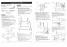
INSTALL POWER CORD BRACKETS (FIG. J)
1. Power cord brackets (1) are provided for convenient
cord storage. Attach the power cord brackets to the back
of the saw body, as shown, with two Phillips head
screws (2).Tighten.
2. Wrap the power cord onto the brackets when the band
saw is'not in use, to prevent damage to the cord.
FIG. J
_ Fy""_
ADJUSTMENT INSTRUCTIONS
To avoid injury, turn the switch OFF and unplug the band saw
from the power source before making any adjustments.
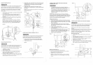
TABLE ADJUSTMENTS (FIG. K, L)
Tilting the table (FIG. K)
The band saw table (1) tilts 0°to 45° to the right
1. Loosen both table lock knobs (2) underneath the table.
2. Tilt the table to the desired angle on the scale (3)
underneath the table.
3. Tighten the two table lock knobs.
FIG. K
1
3
Adjusting the 90 °table stop (FIG. L)
1. Loosen the table lock knobs (2) and tilt the table to
the right.
2. Loosen the nut (4) on the table stop bolt (5) and lower
the stop bolt as far as possible.
3. Tilt the table until it rests on the stop bolt.
4. Place a combination square (6) on the table with the
heel of the square against the saw blade.
5. Adjust the tilt of the table left or r ght unt it is 90° to the
blade. Make sure there is no space between the square
and the blade. Tighten the table lock knobs.
6. Adjust the table stop bolt up until it touches the table.
Tighten the jam nut down to the support bracket.
7. Loosen the lock knobs and see that the table is resting
on the stop bolt.
8. Check the square to make sure the table is still square to
the blade. If not, readjust the stop bolt.
9. When the adjustment is accurate at 90°, align the
pointer (7) to 0° on the scale (8).
FIG. L
6
2 4
8 I
7
10 0 10
.... ...... ¸(i!ii:!ii i:iii!! !?:??ii¸¸:'! ¸¸¸¸¸¸:' :