


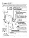
Parts & Features
See figures below for reference.
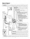
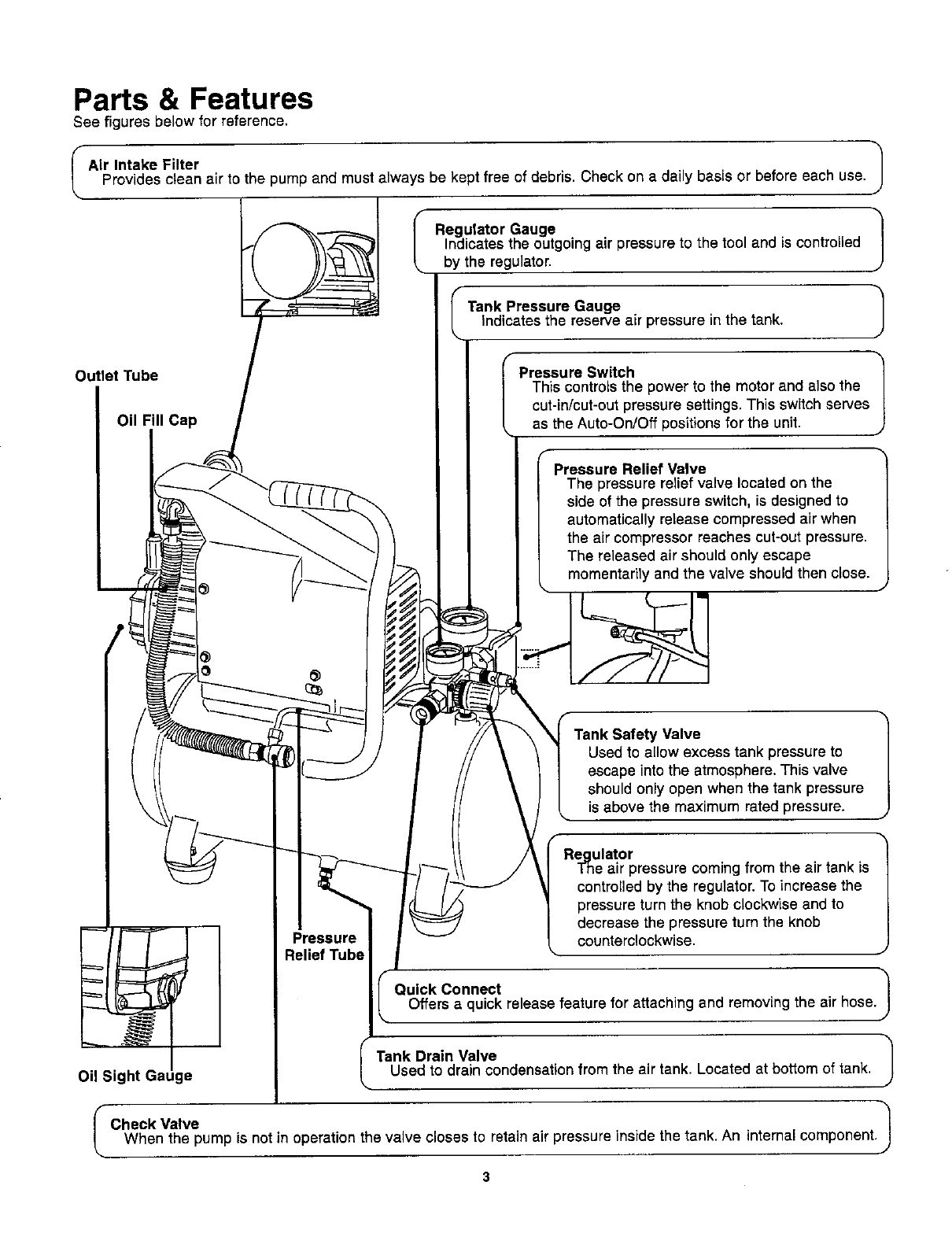
Air Intake Filter
Provides clean air to the pump and must always be kept free of debris. Check on a daily basis or before each use.
I Regulator Gauge
Indicates the outgoing air pressure to the tool and is controlled
by the regulator.
Outlet Tube
Oil Fill Cap
J
Tank Pressure Gauge
Indicates the reserve air pressure inthe tank.
Pressure Switch
This controlsthe power to the motor and also the
cut-in/cut-outpressuresettings. This switchserves
as the Auto-On/Off positionsfor the unit,
Pressure Relief Valve
The pressure relief valve located on the
side of the pressure switch, is designed to
automatically release compressedair when
the air compressor reaches cut-out pressure.
The released air should only escape
momentarilyand the valve should then close.
Oil Sight Gauge
Pressure
Relief Tube
Safety Valve 1
Used to allow excess tank pressure to
escape into the atmosphere.This valve
should only open when the tank pressure
is above the maximum rated pressure.
Re_,.gulator
I ne air pressure coming from the air tank is
controlled by the regulator. To increase the
pressure turn the knob clockwise and to
decrease the pressure turn the knob
counterclockwise.
Quick Connect 1Offers a quick release feature for attaching and removing the air hose.
Tank Drain Valve /
Used to drain condensation from the air tank, Located at bottom of tank.
I Check Valve 1When the pump is not in operation the valve closes to retain air pressure inside the tank. An internal component.