


OM-194 199 Page 7
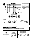
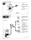
2-5. Installing Work Clamp
1 Work Cable
2 Boot
Slide boot onto work cable. Route
cable out front panel opening from
inside.
3 Negative (–) Output Terminal
Connect cable to terminal and
cover connection with boot.
4 Hardware
5 Work Clamp
Route cable through clamp handle
and secure as shown.
Close door.
ST-801 566-A
1/2, 3/4 in
1
2
3
4
5
Tools Needed:
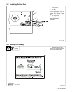
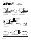
2-6. Installing Gas Supply
ST-801 571 / ST-802 028
Obtain gas cylinder and chain to
running gear, wall, or other station-
ary support so cylinder cannot fall
and break off valve.
1 Cap
2 Cylinder Valve
Remove cap, stand to side of valve,
and open valve slightly. Gas flow
blows dust and dirt from valve.
Close valve.
3 Cylinder
4 Regulator/Flowmeter
Install so face is vertical.
5 Regulator/Flowmeter Gas
Hose Connection
6 Welding Power Source Gas
Hose Connection
Connect customer supplied gas
hose between regulator/flowmeter
gas hose connection, and fitting on
rear of welding power source.
7 Flow Adjust
Typical flow rate is 20 cfh (cubic feet
per hour). Check wire manufactur-
er’s recommended flow rate.
8CO
2
Adapter (Customer Sup-
plied)
9 O-Ring (Customer Supplied)
Install adapter with O-ring between
regulator/flowmeter and CO
2
cylinder.
6
5/8, 1-1/8 in
Tools Needed:
CO
2
Gas
8 9
3
1
2
4
5
7
1
2
3
Argon Gas
OR