


13
WS-6613 / WS-6613 / WS-6615X
CIRCULAR SAW SAFETY
■ Kickback is a result of tool misuse and/or
incorrect operating procedures or conditions
and can be avoided by taking proper precau-
tion as given below.
PREVENTION OF KICKBACK
■ Maintain a firm grip with both hands on the
saw and position you arms to resist kickback
forces. Position your body to either side of the
blade, but not in lime with the blade. Kickback
could cause the saw to jump backwards, but kick-
back forces can be controlled by the operator, if
proper precautions are taken.
■ When blade is binding, or when interrupting a
cut for any reason, release the trigger and hold
the saw motionless in the material until the
blade comes to a complete stop. Never attempt
to remove the saw from the work or pull the saw
backward while the blade is in motion or KICK-
BACK may occur. Investigate and take corrective
actions to eliminate the cause of blade binding.
■ When restarting a saw in the workpiece, center
the saw blade in the kerf and check that teeth
are not engaged into the material. If saw blade
is binding, it may walk up or KICKBACK from the
workpiece as the saw is restarted.
■ Support large panels to minimize the risk of
blade pinching and kickback. Large panels tend
to sag under their own weight. Supports must be
placed under the panel on both sides, near the line
of cut and near the edge of the panel.
■ Do not use dull or damaged blades.
Unsharpened or improperly set blades produce
narrow kerf causing excessive friction blade bin-
ding and kickback.
■ Blade depth and bevel adjusting locking levers
must be tight and secure before making cut.
If blade adjustment shifts while cutting, it may
cause binding and kickback.
■ Use extra caution when making a "plunge cut"
into existing walls or other blind areas.
The protruding blade may cut objects that can
cause kickback.
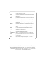
DESCRIPTION
1. Spindle lock button 12. Depth lock knob
2. Hex-head bolt 13. Base plate
3. Spanner 14. Depth of cut
4. Outer blade washer 15. Depth scale
5. Lower guard 16. Bevel adjustment knob
6. Lower guard lever 17. Bevel scale
7. Upper guard 18. Trigger switch
8. Blade 19. Safety button
9. Inner blade washer 20. Line guide
10. Dust nozzle 21. Depth adjustment lug
11. Riving knife
SPECIFICATIONS
WS-6613 / WS-6615 / WS-6615X
Blade diameter 190 mm
(Use only blades of this diameter)
Blade bore diameter 30 mm
Max. thickness of blade disc 2.2 mm
Max. cutting capacities
at 0° 66 mm
at 45° 50 mm
Frequency 50 Hz
Voltage 110V, 230V AC
Input
WS-6613 1,300 W
WS-6615 / WS-6615X 1,500 W
No load speed
WS-6613 4,600/min
WS-6615 / WS-6615X 5,500/min
Net weight
WS-6613 / WS-6615X 5.1 kg
WS-6615 5.3 kg
STANDARD ACCESSORIES
Saw blade, Dust nozzle, Spanner.
APPLICATION
Sawing wood.
NOISE BUILD-UP
Noise (sound pressure level) in the workplace can
exceed 85 dB. In this case, sound insulation and hearing
protection measures must be taken by the operator.
ASSEMBLY INSTRUCTIONS
BE SURE TO DISCONNECT THE TOOL FROM
THE POWER SUPPLY BEFORE ATTACHING
OR REMOVING THE SAW BLADE. BE SURE THAT
THE TEETH OF THE SAW BLADE ARE POINTING
UPWARD AT THE FRONT OF THE TOOL.
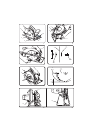
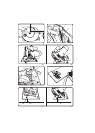
ATTACHING AND REMOVING
THE BLADE (FIGURES 2, 3, 4, AND 5)
TTACHING THE BLADE
1. Pressing the spindle lock button (1), turn the hex-head
bolt (2) with the spanner (3) until the spindle locks.
(Fig.2)
2. Loosen the hex-head bolt by turning the spanner
anticlockwise while pressing the spindle lock button.
(Fig.2)
3. Remove the hex-head bolt and the outer blade
washer (4). (Fig. 2)
4. Retract the lower guard (5) back with the lower guard
lever (6) as far as possible under the upper guard (7).
(Fig. 3)
5. Then, attach the saw blade (8) against the inner blade
washer (9) on the spindle. Then fit the outer blade
washer and the hex-head bolt. (Fig. 3 and 4)
GB