


Copyright © 2011 CyberPower Systems, Inc.
4
BASIC OPERATION
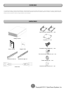
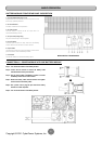
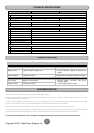
BATTERY MODULE FRONT/REAR PANEL DESCRIPTION
1. On-board Replaceable Fuse Cover
Replaceable fuse is accessible from the rear panel. It must
be done by qualified personnel.
2. AC Circuit Breaker
Provides overload and fault protection.
3. AC Output Outlet
Use this outlet to connect to the AC Input Inlet of a
downstream Battery module.
4. AC Input Inlet (Charge Only)
AC power connectivity to wall receptacle.
5. Input Connector
Use this input connector to daisy chain the next Battery
module. Remove the connector cover for access.
6. Output Cable
Use this output cable to connect the Battery module to the
power module or to the next Battery module.
7. DC Breaker
Use the DC breaker to disconnect battery output.
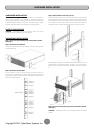
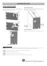
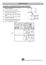
BP240V30ART3U / BP240V50ART3U
CONNECTION #1 : POWER MODULE WITH ONE BATTERY MODULE
Step 1: Turn off the DC breaker of the Battery module.
Step 2: Loosen the two screws to remove the battery cable
retention bracket of the power module.
Step 3: Use the output cable of the Battery module to connect
the Battery module to the Power module.
Step 4: Rotate the battery cable retention bracket and tighten
the two screws to fix battery cable.
Step 5: Use a power cord to plug AC input inlet of the battery
module into a wall receptacle.
Step 6: Turn on the DC breaker of the Battery module.