


AN2309
November 25, 2007 Document No. 001-17394 Rev. *B - 12 -
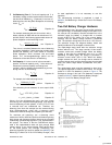
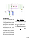
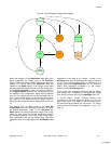
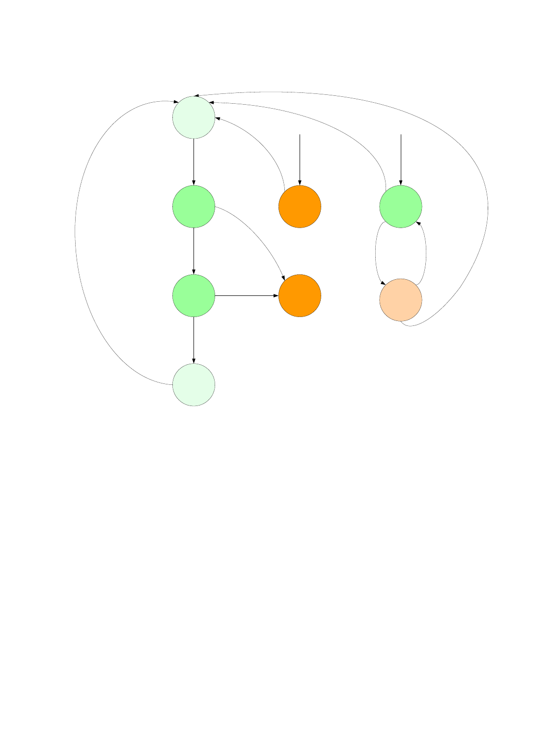
Figure 8. Two-Cell Battery Charger State Diagram
Activation
Initialization
Rapid Error
Charge
Complete
Wait For
Temperature
Full
Discharge
Discharge
1
7
4
5
8
3
2 1211
9
10
6
13
Initially the charger is in the Initialization state. After some
device preparation, the charger goes to the Activation
state (1). When the battery voltage reaches the rapid start
voltage, the charger leaves the Activation state and
switches to the Rapid state (2). If the charge current drops
below a predefined charge-terminate level, the charger goes
to the Charge Complete (3) state. The charger remains in
the Charge Complete state and the charging process can
be restarted if the voltage drops below some predefined
level (8). The charging process can be terminated with an
error if a total charge time-out or an operation charge time-
out occurs, or if the battery voltage or charge current is
higher than the charge termination voltage/current levels (4),
(5).
The charger from all states jumps to the Wait For
Temperature state when the battery temperature is outside
the allowed temperature range. For the Activation and
Rapid states, the allowed temperature range is the charge
range. For other states, the allowed temperature range is
the discharge range (6). In the case of the charge range,
when temperatures fall into the defined range with some
hysteresis value, the charger goes to the Initialization state
(7).
Regardless of the state of the charger, it jumps to the
Discharge state when the external power supply is switched
off (9). If the external power supply is switched on, the
charger goes to the Initialization state (10, 13). When the
battery pack discharges completely (11), the charger
switches to the Full Discharge state.
If the system load resistance decreases and the battery
pack voltage level re-establishes to the predefined voltage
level, then the charger returns to the Discharge state (12).
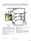
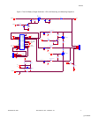
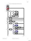
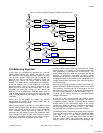
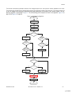
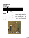
A two-cell battery charger firmware flowchart that
corresponds to the state diagram is shown in Figure 9 on
page 13 and Figure 10 on page 14. The invocation points of
the cell-balancing procedures are also shown. The charge
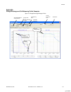
profile example is presented in the Appendix, Figure 13 on
page 18.
[+] Feedback