


AN2309
November 25, 2007 Document No. 001-17394 Rev. *B - 3 -
Temperature gradient across the battery pack.
Temperature mismatches of 15 degrees Celsius can
cause up to 5- percent capacity differential among cells.
Such a temperature gradient is relatively common in
densely packed products, where multiple heat sources
are located close to the battery pack. An example of
this is a laptop computer.
The main causes of variation in cell charge levels are:
Variations in self-discharge rates. Even at room
temperature, two similar cells self-discharge at different
rates, resulting in a mismatch. For example, one cell
could lose 3 percent per month, while another cell loses
a different amount.
Variations in internal cell impedance. These impedance
variations cause otherwise similar battery cells to have
different charge acceptance levels. This error is minute
(about 0.1 percent).
Cell balancing is achieved by connecting a parallel load to
each cell that must be balanced. Typically, a series
combination of a power transistor (MOSFET) and a current-
limiting resistor are connected in parallel to each cell. If a
cell has a higher voltage than the other cells, the bypass
load to the cell is connected by closing the MOSFET so that
a fraction of the charging current bypasses that cell. It is
possible to balance the cells during the discharge phase, the
charge phase, or both phases.
Balancing the charge levels among cells must be done
during the charge or discharge phase. This balancing
process is simple and has been well investigated. Balancing
the cells’ capacity variation must be done during both the
charge and discharge phases. Cells with different capacities
must be charged or discharged by using an absolute value
rather than a relative value. The process of balancing cell
capacity variation is difficult to implement in practice and is
not intuitively obvious.
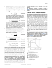
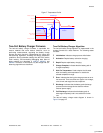
The charge in dV/dQ for Li-Ion batteries has a maximum
level when the cells are nearly fully charged or discharged. It
takes less time to correct voltage mismatch during this
period of complete or nearly complete charge/discharge
than during the middle period of battery charge/discharge.
Thus, it is advisable to perform the balancing routine when
the cells are nearly fully charged or nearly fully discharged.
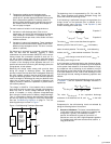
See also Cell-Balancing Algorithm on page 14. The cell-
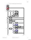
balancing technique is shown in Figure 1.
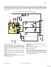
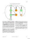
Figure 1. Cell-Balancing Technique Schematic
Charger,
Monitor,
Safety,
Fuel Gauge,
Cell Balance
Software
Load
R1
R2
Q1
Q2
CELL1
CELL2
The balancing circuit is represented by (R1, Q1) and (R2,
Q2). These transistors and resistors dissipate energy and
control the amount of balancing current.
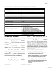
If cell balancing is performed during the charge phase, the
charge current on the balanced cells is reduced on the
shunted current value (Equation 7 and Equation 8) and
remains unchanged on other cells:
V
cellN
I
balN
RR
N QN
Equation 7
I I I
chargeN charge balN
Equation 8
The value
I
balN
is the current that flows through the
balancing circuit of the cell N, and
V
cellN
is the battery
electro chemical potential. The value
R
N
is the balancing
resistor, and
R
QN
is the transistor resistance. The value
I
chargeN
is the charge current of cell N, and
I
charg e
is
the battery pack charge current.
If cell balancing is performed during the discharge phase,
the current that flows through the balancing circuit depends
on the system load resistance. If the load resistance is high,
by comparison with a balancing circuit resistance, most of
the discharge current flows through the balancing circuit. But
if the load resistance is low, most of the discharge current
flows through the load, making the balancing operation less
efficient.
The current that flows through the balancing circuit is shown
in Equation 7 and the equivalent discharge resistance is
equated as:
()R R R
N QN load
R
dischargeN
R R R
N QN load
Equation 9
The value
R
dischargeN
is the equivalent discharge
resistance of the balanced cell N, and
R
load
is the load
resistance.
Components for the cell-balancing circuit are selected by
taking the following factors into account:
Amount of Imbalance: This factor is described earlier
in this section and consists of variations in capacity and
charge level. Typically, cell imbalance is about 1
percent. An imbalance as great as 5 percent to 15
percent can occur only with a high temperature gradient
or if a battery pack has been stored and not used for a
long period of time.
[+] Feedback