


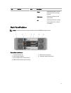
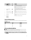
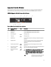

Item Indicator, Button, or
Connector
Icon Description
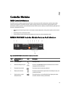
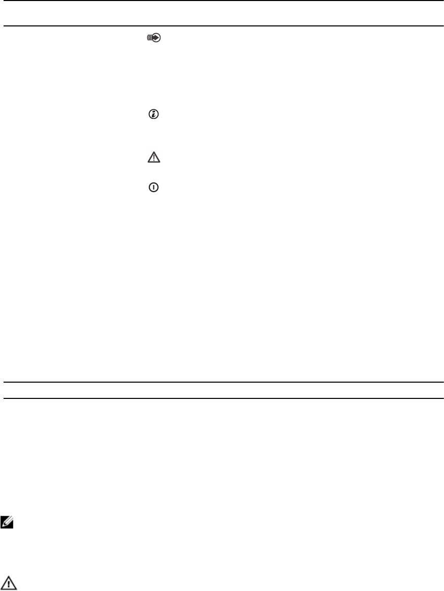
5 Cache active or cache
offload indicator
The cache active or cache offload indicator lights green when on-
board controller memory contains data.
If AC power fails, this LED changes to indicate cache offload
status.
If the password reset function has successfully changed the
password, this LED flashes on and off briefly.
6 System identification
indicator
The system identification indicator blinks blue when system
identification switch push-button on the enclosure front panel is
pressed.
7 Controller fault indicator The controller fault indicator lights amber when controller fault is
detected.
8 Controller power indicator The controller power indicator lights green when controller power
is on.
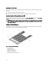
9 SAS OUT port Provides SAS connection for cabling to a downchain expansion
enclosure.
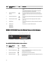
10 FC IN port 0
FC IN port 1
FC IN port 2
FC IN port 3
Provides host-to-controller FC connection.
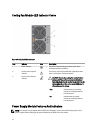
Host Channel LED Link Rate Indications
Below each FC port is a pair of LED indicators. The status of any FC port can be determined by applying the condition of
each LED pair.
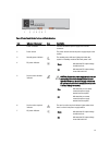
Table 1. LED Status Indicators
LED 1 LED 0 Port Status
Off Off Link down
Off On 2 Gbps link
On Off 4 Gbps link
On On 8 Gbps link
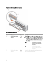
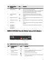
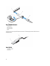
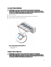
SFP Transceivers Fibre Optic And SAS Cables
NOTE: Your small form-factor pluggable (SFP) transceivers and cables may look different from the ones shown
below. The differences do not affect the performance of the SFP transceivers.
FC host connections may operate at 8 Gbps or at a lower data rate. Ports for 8 Gbps Fibre Channel host connections
require SFP transceivers designed for this data rate. SFP transceivers that support other data rates are incompatible.
WARNING: Do not disassemble or remove any part of a SFP transceiver due to the possibility of being exposed to
Laser radiation.
19