


9
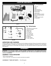
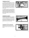
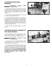
ASSEMBLING STAND
1. Assemble the two legs (A) and (B) Fig. 2, to the band
saw base using the six 5/16-18x1" hex head cap
screws, three of which are shown at (C) Fig. 2, twelve
5/16" flat washers and six 5/16-18" hex nuts. Align the
holes in the band saw with the holes in the legs. Place a
5/16" flat washer onto a 5/16-18x1" hex head cap
screw, insert screw through the hole in the band saw
and the hole in the leg, place a 5/16" flat washer onto
the screw, thread a 5/16" hex nut onto the screw, and
tighten securely. Repeat this process for the five
remaining holes.
2. Assemble the shelf (D) Fig. 2, to the two legs (A) and
(B). Align the four holes in the shelf (D) with the four
holes in the two legs (A) and (B). Insert a M6x10mm hex
head screw, two of which are shown at (E) through the
hole in the shelf and leg. Place a 6mm lockwasher onto
the screw, thread a M6 hex nut onto the screw, and
tighten securely. Repeat this process for the three
remaining holes.
Fig. 2
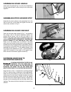
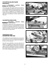
ASSEMBLING WHEELS
Assemble the wheel assembly (A) Fig. 3, to the bottom
of the left leg. Align the holes in the wheel assembly with
the holes in the left leg. Place a 1/4" flat washer onto a
1/4-20x1/2" hex head screw, insert the screw through
the holes (B) in the wheel assembly and the hole in the
left leg, place a 1/4" flat washer onto the screw, thread
a 1/4-20 hex nut onto the screw, and tighten securely.
Repeat this process for the remaining hole.
Fig. 3
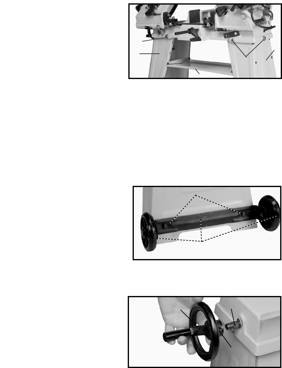
ASSEMBLING VISE HANDWHEEL
Assemble the vise clamping handwheel (A) Fig. 4, to the
shaft (B), and tighten set screw (C) against the flat on the
shaft (B).
Fig. 4
B
C
D
E
A
C
B
A
A
B
C