


17
CHECKING, RESETTING
AND REPLACING KNIVES
When checking, resetting and replacing knives, proceed
as follows:
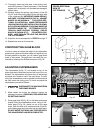
1. DISCONNECT THE MACHINE FROM
THE POWER SOURCE.
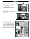
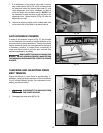
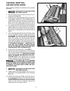
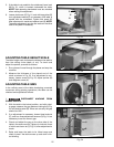
2. Remove locking screw and raise top cover (A) Fig. 33,
to expose cutterhead (B).
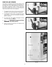
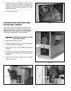
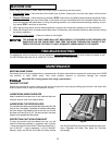
3. Carefully place knife setting gage (C) Figs. 34 and 35,
so the gage is positioned on the radiused section of
cutterhead (B). When set correctly, knife (D) Figs. 34
and 35, should just contact the bottom of inset section
(E) Fig. 35 of knife setting gage (C) which is set at
.070 . Check the remaining knives in the same manner.
4. If an adjustment to one or all three knives is necessary,
slightly loosen the 12 locking screws, one of which is
shown at (F) Fig 34 and also in Fig. 35, just enough to
relieve stress in cutterhead (B) and not disturb the knife
setting.
5. With knife setting gage (C) Figs. 34 and 35 still in place
on the cutterhead, continue to adjust the knife that
must be reset by turning the 12 knife locking screws
CLOCKWISE until knife locking bar (G) becomes
loose. Lifter springs (not shown) located under the
knife will automatically raise the knife until it comes in
contact with the gage (C). Then snug up the knife lock-
ing bar (G) Fig. 34 and Fig. 35, by turning the ten screws
(F) COUNTERCLOCKWISE. IMPORTANT: AT
THIS TIME, ONLY TIGHTEN THE KNIFE LOCKING
BAR (G) JUST ENOUGH TO HOLD THE KNIFE (D) IN
POSITION INSIDE THE CUTTERHEAD SLOT.
6. If other knives need adjustment, repeat STEP 5.
7. After all the knives are positioned in the cutterhead
with the knife locking screws snug, turn each of the 12
locking screws (F) Fig. 34, COUNTERCLOCKWISE
UNTIL THE KNIVES ARE SECURE IN THE CUT-
TERHEAD. NOTE: When tightening the knife locking
screws (F), tighten the end screws first, then proceed
inward toward the center of the cutterhead.
IF THE KNIVES ARE TO BE REMOVED
FOR SHARPENING OR REPLACEMENT, EXTREME CARE
SHOULD BE TAKEN AS THE KNIVES ARE VERY SHARP.
TO REMOVE THE KNIVES, WEAR GLOVES AND PRO-
CEED AS FOLLOWS:
8. DISCONNECT THE MACHINE FROM
THE POWER SOURCE.
9. Carefully place knife setting gage (C) Fig. 34, so it is
positioned on the radiused section of the cutterhead
(B) Fig. 35.
10. Loosen knife locking bar (G) Figs. 34 and 35, by turn-
ing 12 knife locking screws, 10 of which are shown at
(F) CLOCKWISE and carefully remove locking bar (G),
knife (D), and springs (not shown) which are located
under the knife, from the cutterhead. Remove the
remaining knives in the same manner.
Fig. 33
Fig. 34
A
B
G
F
B
C
D