


20
1. DISCONNECT THE MACHINE FROM
THE POWER SOURCE.
2. Make certain the knives are adjusted properly as
explained in section “CHECKING, ADJUSTING
AND REPLACING KNIVES.”
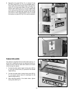
3. Place gage block (A) Fig. 46, on the table, directly
under the cutterhead (B). Using a .040” feeler gage
(C) placed on top of the gage block (A), raise the
table until the cutterhead knife just touches feeler
gage (A) when the knife is at its lowest point. NOTE:
Do not move the table any further until the adjust-
ment is complete.
Fig. 44
Fig. 46
ADJUSTING INFEED ROLLER
The infeed roller feeds the stock into the planer while the
stock is being surfaced. The infeed roller must be posi-
tioned uniformly across the planer and .040” below the
cutting circle to feed the stock without slipping. To
check the setting of the infeed roller, proceed as follows:
A
D
C
A
B
Fig. 43
C
A
B
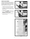
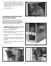
ADJUSTING OUTFEED ROLLER
The outfeed roller continues to feed the stock out of the
machine after the planing operation has been completed
and should be set at .030” below the cutting circle.
To check and adjust the setting of the outfeed roller, pro-
ceed as follows:
1. DISCONNECT THE MACHINE FROM
THE POWER SOURCE.
2. Make certain the knives are adjusted properly as
explained in section “CHECKING, ADJUSTING AND
REPLACING KNIVES.”
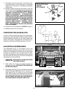
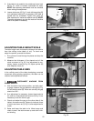
3. Place gage block (A) Fig. 43, on the table, directly
under cutterhead (B). Using a .030” feeler gage (C)
placed on top of gage block (A), raise the table until
the cutterhead knife just touches feeler gage (A) when
the knife is at its lowest point. NOTE: Do not move the
table any further until the adjustment is complete.
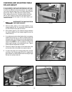
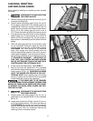
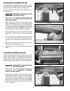
4. Place gage block (A) Fig. 44, under outfeed roller (D).
The bottom of roller (D) should just touch gage block
(A).
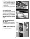
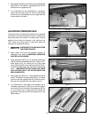
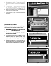
5. If an adjustment is necessary, loosen locknut (E)
Fig. 45, and turn adjustment screw (F) until the out-
feed roller just touches the top of gage block (A) Fig.
44.
6. Repeat the adjustment on the opposite end of the
outfeed roller in the same manner.
7. Tighten locknuts (E) Fig. 45 after adjustments are com-
pleted.
Fig. 45
F
E
F
E