


6
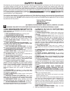
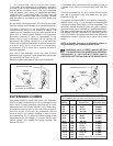
Fig. 7
2. Align the holes in the eye shield with the holes in the
spark guard and place the eye shield bushing (A) Fig. 7,
in between the space in the spark guard.
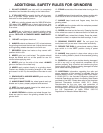
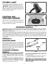
Fig. 8
3. Insert the eye shield bolt (A) Fig. 8, through the hole
in the eye shield (B), eye shield bushing (C), and spark
guard (D).
4. Place an 11/16" flat washer (E) Fig. 8, onto the end
of the eye shield bolt and fasten the eye shield knob (F)
to the end of the eye shield bolt.
5. Assemble the other eye shield in the same manner.
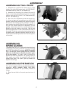
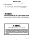
FASTENING GRINDER TO
SUPPORTING SURFACE
Fig. 9
IF DURING OPERATION THERE IS ANY TENDENCY
FOR THE GRINDER TO TIP OVER, SLIDE OR
“WALK,” THE GRINDER MUST BE SECURED TO THE
SUPPORTING SURFACE USING FASTENERS (NOT
SUPPLIED) THROUGH THE TWO HOLES (A) Fig. 9, IN
THE GRINDER BASE.
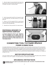
CONNECTING TOOL TO POWER SOURCE
POWER CONNECTIONS
A separate electrical circuit should be used for your tools. This circuit should not be less than #12 wire and should
be protected with a 20 Amp time lag fuse. If an extension cord is used, use only 3-wire extension cords which have
3-prong grounding type plugs and 3-hole receptacles which accept the tool’s plug. Before connecting the motor to
the power line, make sure the switch is in the “OFF” position and be sure that the electric current is of the same
characteristics as indicated on the tool. All line connections should make good contact. Running on low voltage will
damage the motor.
MOTOR SPECIFICATIONS
Your tool is wired for 120 volt, 60 HZ alternating current. Before connecting the tool to the power source, make sure
the switch is in the “OFF” position. The motor provides a no-load speed of 3450 RPM.
GROUNDING INSTRUCTIONS
WARNING: THIS TOOL MUST BE GROUNDED WHILE IN USE TO PROTECT THE OPERATOR FROM
ELECTRIC SHOCK.
A
A
A
A
B
C
D
E
F