


8
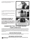
STARTING AND
STOPPING GRINDER
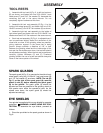
The switch (A) Fig. 14, is located on the front of the
grinder. To turn the grinder “ON” move the switch to the
up position. To turn the grinder “OFF” move the switch
to the down position.
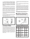
DRESSING A
GRINDING WHEEL
When dressing a grinding wheel, use a suitable silicone
carbide stick type dresser or the wheel dresser wrench
provided with the grinder, as shown in Fig. 16. Bring the
dresser forward on the tool rest until it just touches the
high point on the face of the wheel and dress the wheel
by moving the dresser back and forth. Repeat this
operation until the face of the grinding wheel is clean and
the corners of the wheels are square.
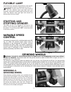
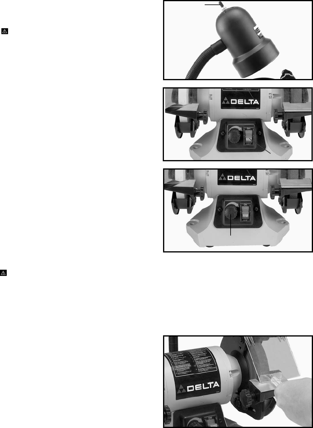
FLEXIBLE LAMP
The flexible lamp operates independently of the grinder.
To turn the lamp on and off, rotate switch (A) Fig. 13.
WARNING: To reduce the risk of fire, use 40 watt or
less, 120 volt, reflector track type light bulb (not
supplied). A standard household light bulb should not be
used. The reflector track type light bulb should not
extend below the lamp shade.
GRINDING WHEELS
WARNING: THE USE OF ACCESSORIES AND ATTACHMENTS NOT RECOMMENDED BY DELTA MAY RESULT
IN RISK OF INJURIES. Attachments used with this grinder should be rated for 3600 RPM or higher and be 6" in
diameter with a 1/2" arbor hole.
Two aluminum oxide grinding wheels are supplied with your grinder; one 36 grit and one 60 grit. For best grinding
results, and to maintain good balance, always keep the wheels properly dressed. Do not force the work against a cold
wheel. The grinding wheel should always be run at idle speed for one full minute before applying work. It is
recommended that only balanced wheels be used with your grinder. The use of balanced wheels adds years to the life
of the bearings on the grinder and by eliminating the most common source of vibration, more accurate work is
accomplished.
Fig. 13
Fig. 14
Fig. 16
A
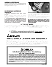
VARIABLE SPEED
CONTROL
The grinder is equipped with a variable speed control (B)
Fig. 15. When the variable speed control knob is
positioned to the furthermost left position (counter
clockwise), the RPM is 2000. The rotation increases as
the knob is turned clockwise. When the variable speed
control knob is positioned to the furthermost right
position (clockwise), the RPM is 3450.
Fig. 15
A
B