


6
ASSEMBLY INSTRUCTIONS
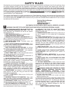
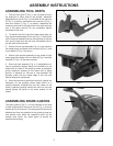
ASSEMBLING TOOL RESTS
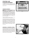
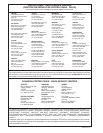
1. The tool rest arms (F) Fig. 3, are universal and can
be attached to either side of the grinder. Assemble
adjustable tool rest (J) Fig. 3, to left side of tool rest arm
(F) Fig. 3, as shown, and fasten with one bolt (1) Fig. 2,
and one washer (7) Fig. 2, as shown. Assemble the
remaining tool rest to the right side of the other tool rest
arm in the same manner. Do not completely tighten
hardware at this time.
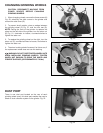
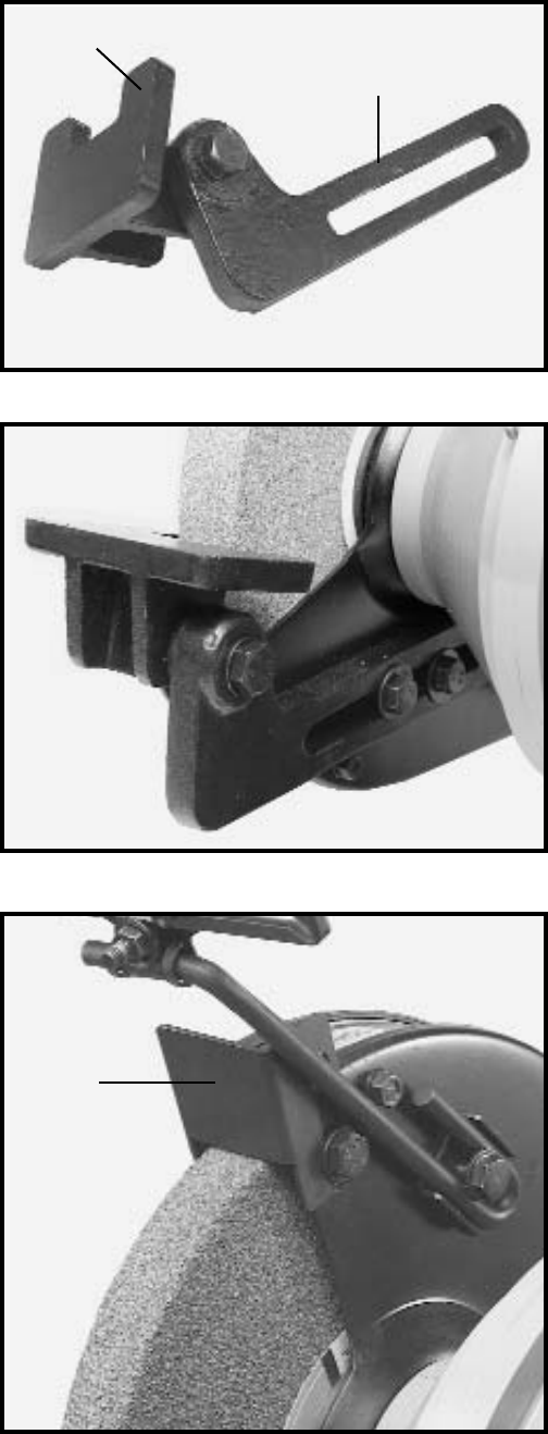
2. To identify the left & right tool rests place them, as
they would be assembled on the tool Fig. 4. The left tool
rest will have a threaded hole on the right side of the tool
rest, and the right tool rest will have a threaded hole on
the left side of the tool rest.
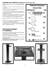
3. Attach left tool rest assembly Fig. 4, to the inside of
left wheel guard, and fasten with two bolts (2) Fig. 2, and
two washers (7) Fig. 2 as shown.
4. Attach right tool rest assembly to the inside of right
wheel guard and fasten with two bolts (2) Fig. 2 and two
washers (7) Fig. 2 in the same manner.
5. Each tool rest assembly Fig. 4, is adjustable so it
can be positioned slightly below the centerline of the
wheel and as close to the grinding wheel as possible,
giving maximum support to the piece that is being
ground. A distance of 1/8-inch or less between the
grinding wheel and the inside edge of the tool rest
should always be maintained.
6. When the tool rest is positioned correctly, tighten the
hardware. As the grinding wheel wears down to a
smaller diameter, re-adjust the tool rest closer to the
wheel. Freehand grinding without the use of a tool rest
should always be done on the lower quarter of the
wheel.
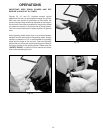
ASSEMBLING SPARK GUARDS
The spark guard (I) Fig. 5, is to be mounted to the side
of each wheel guard, using one bolt (4) Fig. 2, and one
washer (8) Fig. 2 as shown. The spark guard (I) should be
adjusted as close as possible to the grinding wheel so
that sparks never strike the operator’s hand. As the
wheels wear down, the spark guard (I) should be
adjusted accordingly.
Fig. 3
J
F
Fig. 4
Fig. 5
I