


11 - English
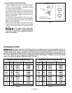
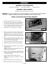
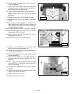
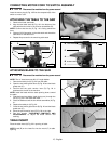
14. Align the holes in the base (A) Fig. 8, with the holes
in the two sides (B).
15. Insert a hex head flange screw (M8x1.25x16mm)
through the hole in the side of the stand (B) Fig. 8,
and through the hole in the base (A).
16. Thread a hex flange nut (M8x1.25) on the screw.
NOTE: Loosely tighten the hardware for further
adjustment.
17. Repeat this process for the five remaining holes.
18. Attach the other side of the base in the same
manner.
19. Attach the two bases together by inserting a hex
head flange screw (M8x1.25x16mm) through the
hole (C) Fig. 8 in each base, and thread a hex flange
nut (M8x1.25) on the screw.
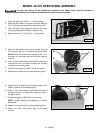
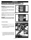
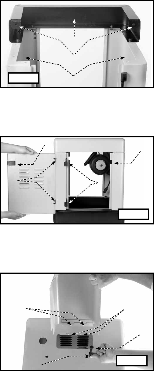
20. Turn the stand over so that it is resting on the base.
21. Slide the two hinges of the door (A) Fig. 9 over the
hinge catches (B) on the stand.
22. Close the door until the door latch (C) Fig. 9,
engages with the side (D).
23. Attach the other door in the same manner.
A
B
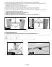
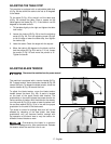
24. Thread a hex nut (M10x1.5) on a hex head screw
(M10x1.5x100mm) approximately 1/4".
25. Thread the hex head screw (C) into the hole (A) Fig.
10 in the top of the stand.
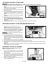
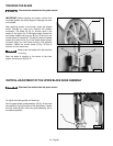
26. Place the damping cap (A) Fig. 10A on the threaded
end of the screw (C).
27. Align the holes (D) Fig. 10 on the hinges attached to
the pulley guard with the two holes (B) in the top of
the stand.
28. Insert a pan head screw (M5x0.8x10mm) through
the hole (D) Fig. 10 in the hinge, and the hole (B) in
the top of the stand.
29. Thread a hex nut (M5x0.8) on the screw and tighten
securely.
30. Repeat this process for the remaining hole in the
hinge and the top of the stand.
31. Confirm that the stand is level.
32. Tighten all hardware securely.
C
A
B
C
D
A
C
D
B
Fig. 8
Fig. 9
Fig. 10