


19 - English
1. Confirm that the bottom blade guides and support bearings are not touching the blade.
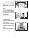
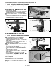
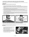
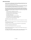
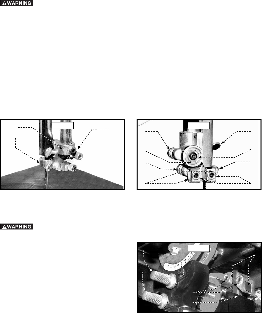
2. Observe the upper blade guide assembly. The blade guides (A) Fig. 34 should be parallel to the blade. To adjust, loosen
the screw (B) and rotate the complete guide assembly (C). When the blade guides are parallel with the blade, tighten the
screw (B).
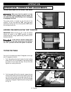
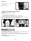
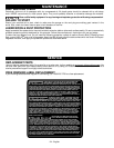
3. Adjust the guides (A) Fig. 35 so that the front edge of the guides are just behind the "gullets" of the saw teeth. You can
move the complete guide block bracket in or out by loosening the thumb screw (C) and turning the knurled knob (D) Fig.
35. When the guides (A) are set properly, tighten the thumb screw (C).
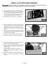
5. Two set screws (B) Fig. 35 hold the upper blade guides (A) in place. Loosen the set screws (B) to move the guides (A).
Place them as close as possible to the side of the blade. (Do not pinch the blade). Tighten the screws (B).
6. The upper blade support bearing (E) Fig. 35 prevents damage to the set in the saw teeth by keeping the blade held
forward. Set the support bearing (E) 1/64" behind the blade. Loosen the thumb screw (F) and turn the knurled knob (G) to
move the support bearing (E) in or out.
7. Adjust the blade support bearing (E) so that the back edge of the blade overlaps the outside diameter of the ball bearing
by about 1/16". The bearing (E) is set on an eccentric. To change the position, remove the screw (H) and bearing (E) Fig.
35. Loosen the thumb screw (F), and back out the knurled knob from the set screw. Remove the hex shaft from the hole,
and rotate it to move the eccentric for the bearing.
8. When the blade guide wears so that it cannot be adjusted close to the blade, loosen the screw (B) Fig. 35 and reverse
the blade guides (A) Fig. 35.
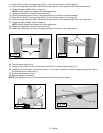
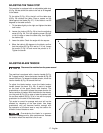
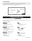
ADJUSTING LOWER BLADE GUIDES AND BLADE SUPPORT BEARING
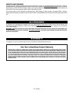
1. Turn the knurled knob (C) Fig. 36 to adjust the front
edge of the guide blocks (B) Fig. 36 so that they are
just behind the "gullets" of the saw teeth.
NOTE: The support bearing (D) Fig. 36 should not be
touching the back of the blade.
2. Loosen the two screws (A) Fig. 36. Move the guides
(B) as close as possible to the side of the blade, being
careful not to pinch the blade. Tighten the screws (A).
3. Turn the other knurled knob (E) to adjust the lower
blade support bearing (D) Fig. 36 so that it is about
1/64" behind the back of the blade.
A
C
B
G
E
D
A
B
C
H
F
A
E
C
D
B
ADJUSTING THE UPPER BLADE GUIDES AND BLADE SUPPORT BEARING
Adjust the upper blade guides and blade support bearings ONLY AFTER the blade has the correct tension and is tracking
properly. To adjust:
Fig. 34
Fig. 35
Adjust the lower blade guides and blade support bearing after the the upper guides and bearing have been adjusted.
Fig. 36
Disconnect the machine from the power source!
Disconnect the machine from the power source!