


5
Fig. 6
Fig. 7
Fig. 8 Fig. 9
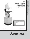
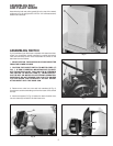
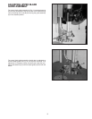
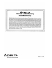
ASSEMBLING BELT
AND PULLEY GUARD
Assemble the belt and pulley guard (A) to the top of the stand,
as shown in Fig. 6, using the two 1/4-20 x 1/2 hex head screws,
washers and nuts (B).
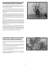
ASSEMBLING SWITCH
If you purchased your band saw complete with stand and elec-
tricals, you received a switch mounted in a switch box and a
cord set connected to the motor. Assemble the switch to the
band saw arm as follows:
1. MAKE CERTAIN THE BAND SAW IS DISCONNECTED
FROM THE POWER SOURCE.
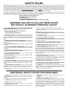
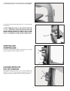
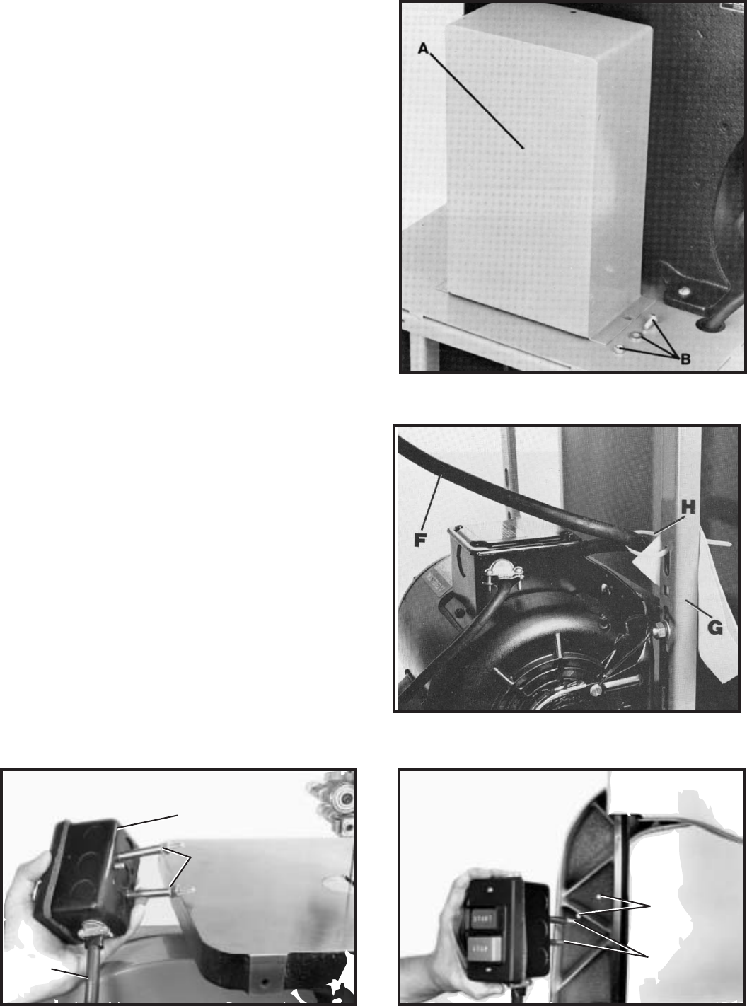
2. CAUTION: THE ON/OFF SWITCH-TO-MOTOR CORD (F)
FIG. 7, IS TIED TO VERTICAL MOUNTING POST (G) OPPO-
SITE THE MOTOR PULLEY. THIS CABLE TIE (H) PREVENTS
THE SWITCH-TO-MOTOR CORD (F), FROM CONTACT-
ING THE BELT OR MOTOR PULLEY DURING OPERATION.
IMPORTANT: DO NOT REMOVE THIS CABLE TIE UNLESS
YOU ARE USING THE ACCESSORY #28-984 HEIGHT
ATTACHMENT WITH THE BAND SAW.
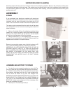
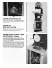
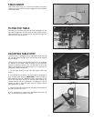
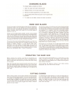
3. Remove two outer hex nuts and lock washers (A) Fig. 8,
from the two screws extending out from the back of the switch
box (B).
4. Insert two screws (C) Fig. 9, located on back of switch box,
into two holes (D) located in the band saw arm.
F
B
A
D
C