6
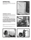
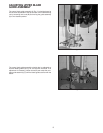
Fig. 10
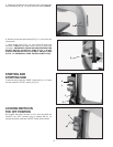
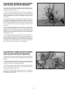
Fig. 11
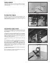
Fig. 12
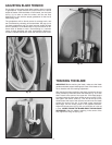
Fig. 13
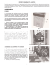
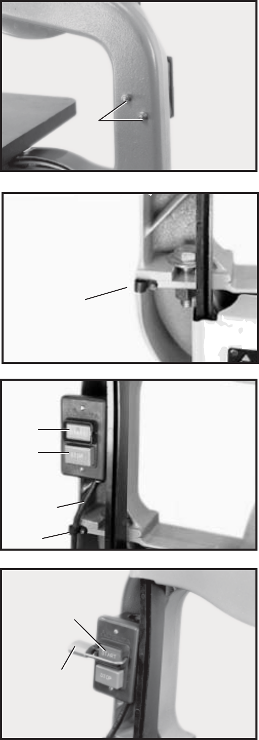
5. Fasten the switch box to the band saw arm using two nuts
and lockwashers (A) Fig. 10, which were removed in STEP 3.
6. Remove screw and cable clamp (E) Fig. 11, from lower arm
of band saw.
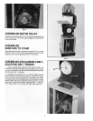
7. Insert switch cord (F) Fig. 12, into clamp (E) which was
removed in STEP 6, and fasten switch cord (F) to band saw
as shown. IMPORTANT: CHECK AND MAKE CERTAIN THE
ON/OFF SWITCH-TO-MOTOR CORD (F) FIG. 7, IS NOT
CONTACTING MOTOR PULLEY OR BELT. ADJUST CORD
(F) FIG. 7, IF NECESSARY, THEN TIGHTEN CABLE TIE (H).
STARTING AND
STOPPING SAW
To start the saw, press the “START” button (K) Fig. 12. To stop
the saw, press the “STOP” button (L) Fig. 12.
LOCKING SWITCH IN
THE OFF POSITION
We suggest that when the saw is not in use, the switch be
locked in the “OFF” position using a padlock (M) Fig. 13,
through the switch plate and “START” button (K) as shown.
E
K
L
F
E
K
M
A


