


8
NOTICE
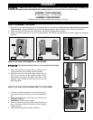
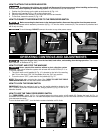
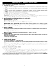
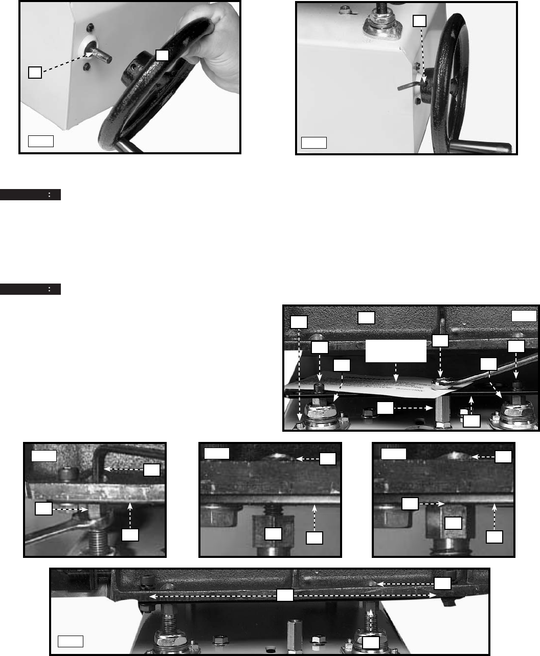
Before you attach the table, remove the front and rear shipping bolts, one shown at (N) Fig. 6 that stabilized
the support plate during transit. Use a 1/2" wrench to hold the hex stop post (S), and another 1/2" wrench to remove the hex
bolts (N).
NOTE: DO NOT remove the hex stop post (S) Fig. 6.
1. The abrasive belt and the motor for the feed table are shipped assembled. Place the feed table (A) Fig. 6 (motor side first)
on the support plate (P). Align the holes in table (two of which are shown at C) with top of the leveling bolts (B).
NOTICE
Confirm that the table is not resting on any of the lockwashers attached to leveling bolts (B).
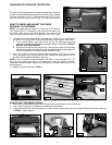
2. Use four 5/16" socket-head bolts with lock washers to
fasten the table assembly (A) Fig. 6 to the support plate
(P) through the holes (D) Secure with flange nuts, two
of which are shown in (F) Fig. 10. Tighten securely.
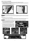
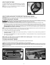
3. Hold the top of the front right leveling bolt (L) Fig. 7 with
a 1/2" wrench. Use a 3/16" hex wrench to loosen the
bolt (B) four full turns. Turn the leveling bolt clockwise
until it no longer touches the support plate (P) Fig. 8.
Turn it counter-clockwise until it touches the support
plate (P) Fig. 9. Do not raise the plate with the leveling
bolt. Hold the top of the leveling bolt (L) Fig. 7 and
tighten hex bolt (B).
HOW TO ATTACH AND LEVEL THE FEED TABLE
A
CAUTION
TAG
Fig. 6
L
Fig. 7
Fig. 8
Fig. 9
Fig. 10
D
C
B
B
C
N
S
P
B
L
P
B
L
P
B
P
L
O
F
A
P
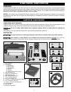
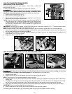
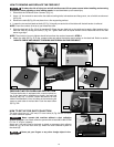
HOW TO ATTACH THE HANDWHEEL
1. Place the handwheel (A) Fig. 4 on shaft (B). Align the set screw with the drilled recess in the shaft.
2. Fasten the handwheel to the shaft by tightening the set screw (C) Fig. 5. Make sure that the set screw contacts the flat
of the shaft and not the O.D. of the shaft.
3. The machine is shipped with the support plate lowered to the bottom. Turn the handwheel counter-clockwise two
turns to raise the support plate off of the bottom stops.
A
Fig. 4
B
Fig. 5
C