


9
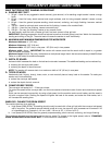
Before connecting the feed motor to the feed-speed switch, disconnect the machine from the power source.
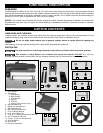
Insert the feed/speed switch assembly connector (A) Fig. 11C into the motor connector (B). The connector is polarized and
will fit only one way.
NOTICE
To avoid damage, DO NOT connect the motor to any other power source.
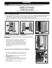
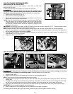
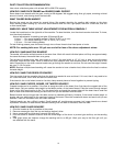
1. The drum motor on/off paddle (A) Fig. 12 is located to the left of the sanding
belt. To turn the drum “ON”, lift the paddle (A) to the “ON” (up) position.
2. To turn the drum “OFF”, push down on the paddle (A) Fig. 12.
NOTE: This switch only controls the drum. See "HOW TO USE THE TABLE
FEED/SPEED SWITCH" for feed table switch instructions.
IMPORTANT: When the machine is not in use, the switch should be locked in the
“OFF” position to prevent unauthorized use, using a padlock (C) Fig. 13 with a 1/4"
diameter shackle.
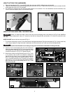
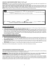
The "FEED/SPEED" switch (A) Fig. 14 is located above the drum motor on/off paddle (B). Rotate the knob (A) Fig. 14
clockwise to turn the table motor on. The table feed/speed rate increases as you turn the knob clockwise. Counter-clockwise
turns decrease the rates.
To turn the feed table “OFF”, turn the knob counter-clockwise until it clicks.
OPERATING CONTROLS AND ADJUSTMENTS
B
A
Fig. 12
Fig. 13
HOW TO START AND STOP THE MACHINE
HOW TO LOCK THE DRUM SWITCH
Fig. 12
HOW TO CONNECT THE FEED MOTOR TO THE FEED/SPEED SWITCH
A
B
B
A
A
HOW TO USE THE TABLE FEED/SPEED SWITCH
Fig. 14
C
NOTICE
Never operate this machine without a dust collection system
attached. Use a dust collection system with at least 400 to 600 CFPM (11.3 to
17 m
3
/min) capacity.
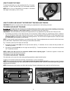
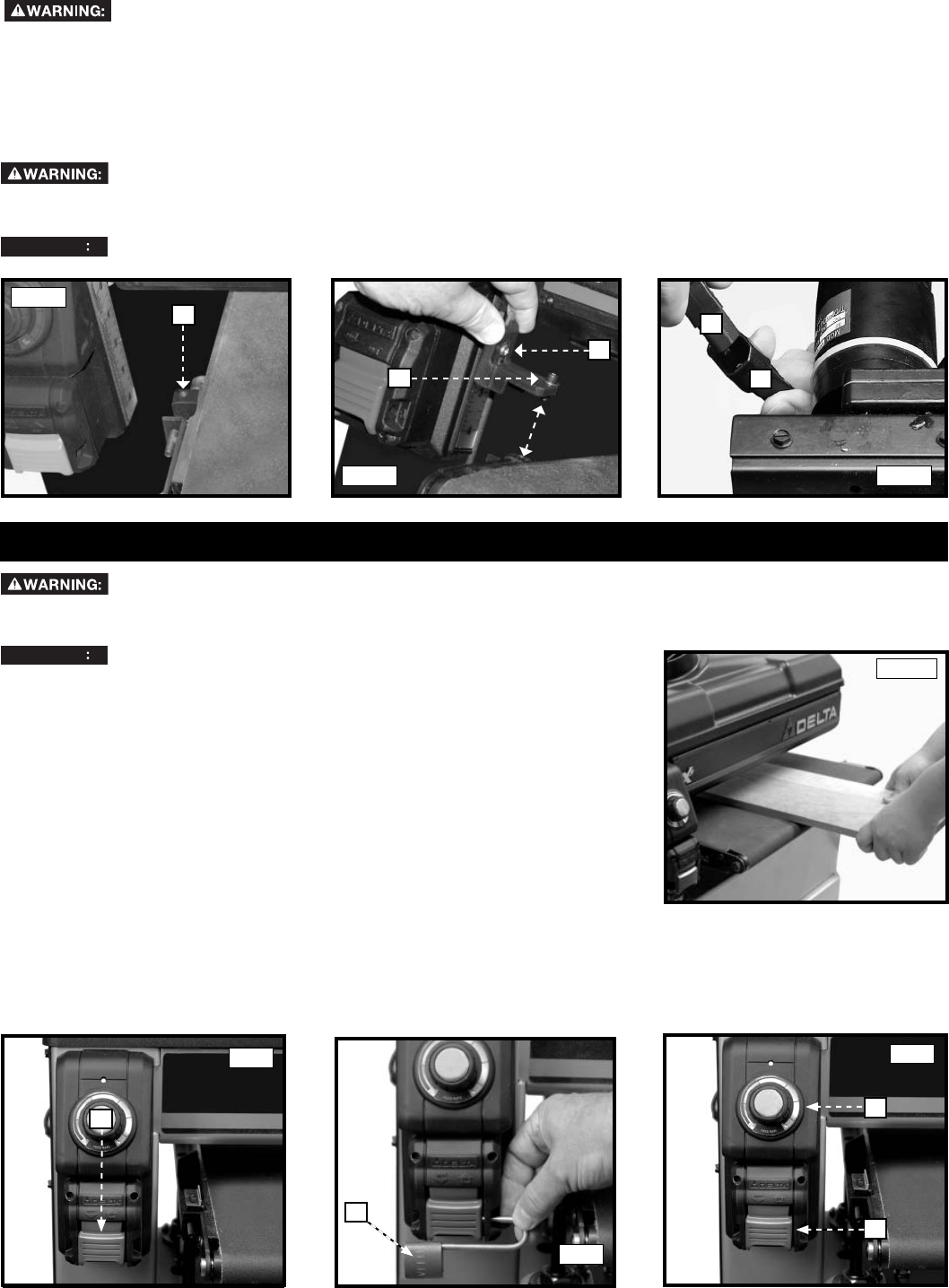
Keep your fingers away from the feed belt, feed rollers, and sanding drum during operation. The correct
hand position is illustrated in Fig. 12A .
Fig. 12A
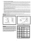
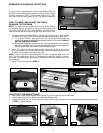
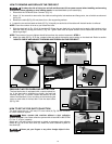
HOW TO ATTACH THE SA FEED INDICATOR
To reduce the risk of injury, turn unit off and disconnect it from power source before installing and removing
accessories, before adjusting or when making repairs. An accidental start-up can cause injury.
1. Position the SA indicator on the table as indicated in (A) Fig. 11A.
2. Place the #10 washer (B) Fig. 11B on the indicator bolt.
3. Securely fasten the SA indicator to the table with the bolt and washer.
4. To fine tune, loosen the screw (C) Fig. 11B.
A
Fig. 11A
Fig. 11C
Fig. 11B
B
C