


7
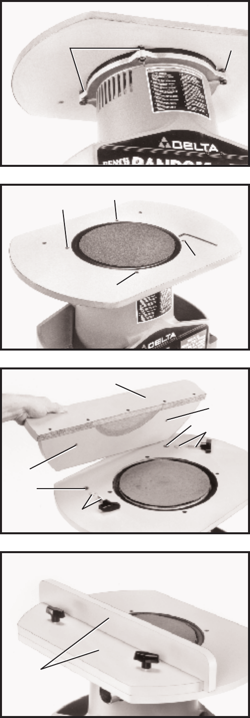
Fig. 8
Fig. 9
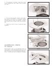
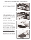
2. If an adjustment is necessary, loosen four lock nut s
located underneath the table, three of which are shown
at (F) Fig. 8.
3. W ith allen wrench supplied, tighten or loosen adjust-
ment screws (D) and (E) Fig. 9, as necessary. Recheck
the table height and repeat the adjustment if needed,
until the t able surface is slightly lower than the abrasive
disc.
4. Tighten four lock nut s (F) Fig. 8, af ter t able height
adjustment.
F
F
D
E
D
E
Fig. 10
Fig. 11
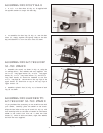
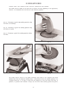
ASSEMBLING FENCE
TO TABLE
Align two holes (A) Fig. 10, in the underside of fence (B)
with two holes (C) in the t able and fasten fence (B) to the
table from the top, with two lock knobs and flat washers (D).
Fig. 11, illustrates the fence (B) assembled to the sander.
A
C
D
A
C
D
B
B