


8
Fig. 13
Fig. 12
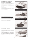
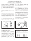
ASSEMBLING DUST B A G
1. A 1-1/2 I.D. dust chute (A) Fig. 12, is supplied with
the spindle sander to accept the dust bag.
2. To assemble the dust bag (B) Fig. 13, over the dust
chute (A), simply squeeze the spring clamp on the dust
bag and assemble it over the dust chute as shown.
Fig. 14
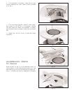
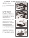
ASSEMBLING ACCESSORY
50-780 STA N D
1. Assemble the stand, as shown in Fig. 14, using the
32 carriage bolts, flat washers and nut s supplied. T he
two 11-1/2 long upper braces (A); 21-5/16 long upper
braces (B); 17-1/8 long lower braces (C); and 26-5/8
long lower braces (D) should be fastened to the four
27-1/2 long legs (E). IMPORTANT:The top lips of the
upper braces (A) should be on top of the top lips of
upper braces (B).
2. Assemble a plastic foot (F) Fig. 14, to bottom of each
leg (E) as shown.
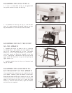
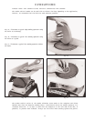
ASSEMBLING SANDER TO
ACCESSORY 50-780 STA N D
If you purchased the accessory 50-780 stand for use with
your sander, carefully place the sander on the st and.
Align the four holes on the top of st and (A) Fig. 15, with
four mounting holes at the base of sander (B) and fasten
sander to the stand with four M8 x 45mm hex head
screws (C), three of which are shown, eight flat washers
and four hex nuts supplied.
Fig. 15
C
B
C
A
B
A
E
D
F
C
A
B
A