


8
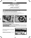
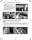
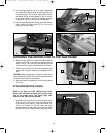
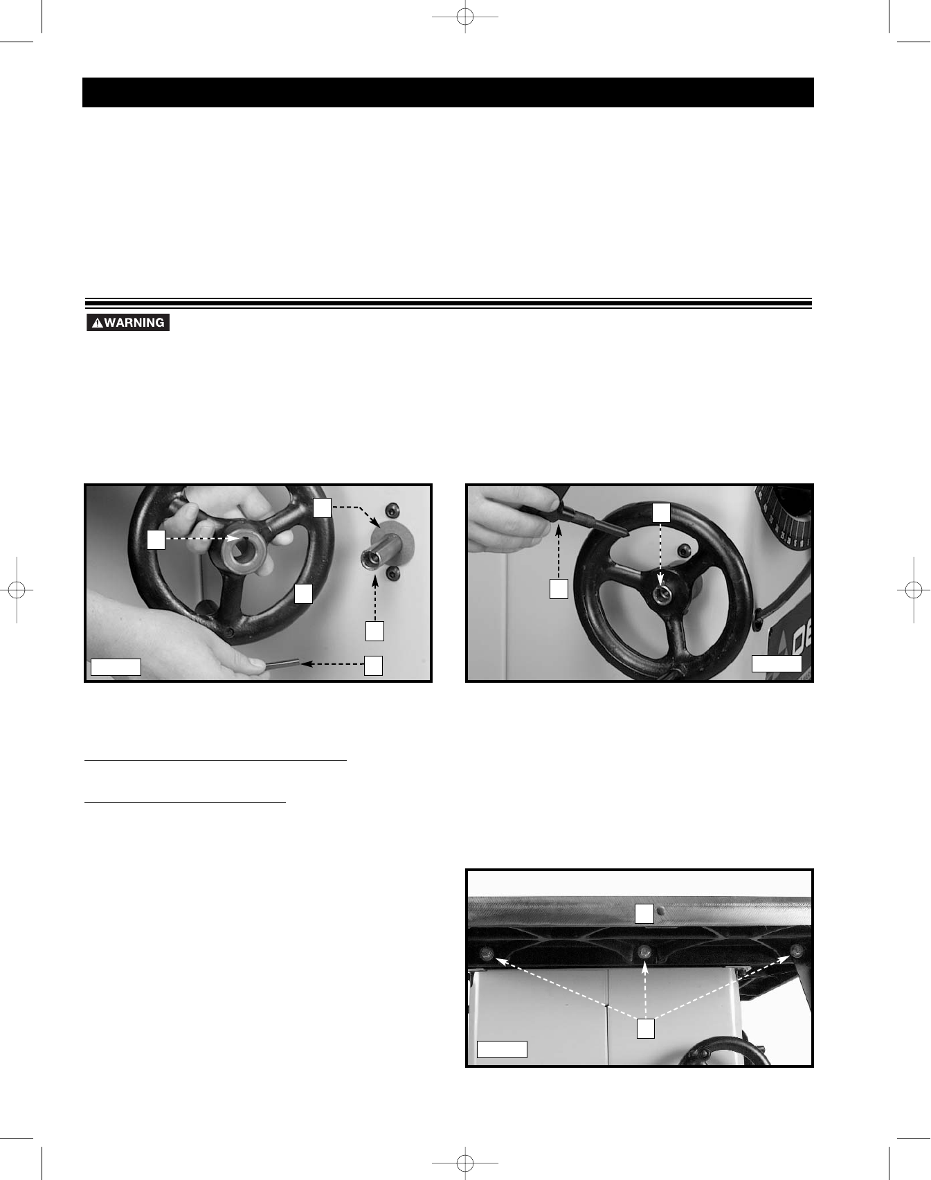
1. Install the fiber washer (A) Fig. 3 on the shaft (B). Install the key (C) into the shaft keyway.
2. Place the handwheel (D) on the shaft (B) Fig. 3. Align the groove (E) in the handwheel with the key (C).
3. Push the handwheel snugly against the fiber washer and tighten the set screw.
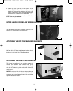
4. Thread the lockknob (F) Fig. 4 into the shaft (B). Hand-tighten lock knob.
A
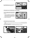
ASSEMBLY
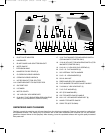
ASSEMBLY TOOLS REQUIRED
ASSEMBLY TIME ESTIMATE
Assembly for this machine takes approximately 1 hour.
For your own safety, do not connect the machine to the power source until the machine is
completely assembled and you read and understand the entire instruction manual.
INSTALLING THE BLADE TILTING HANDWHEEL
B
D
C
E
F
B
Fig. 3
Fig. 4
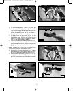
ATTACHING THE EXTENSION WING
NOTE FOR MAGNETIC ST
ARTER BOX: Do not install the front screw and washer when you attach the left
extension wing. You will install those when you attach the "ON/OFF" switch.
NOTE FOR L
VC STARTER BOX: If your Unisaw was shipped with an LVC starter box, remove the LVC “ON/OFF”
switch from the left side of the Unisaw. Save the hardware to attach the “ON/OFF” switch to the left extension
wing in the section “ATTACHING THE LVC ON/OFF SWITCH.”
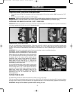
Attach the extension wing (A) Fig. 5 to the left side of the
saw table using three 7/16"-20x1
1
/
4" hex head bolts (B)
and 7/16" flat washers.
NOTE: Make sure that the front edge of the wing is
flush with the front edge of the table.
A
B
Fig. 5
1/8" Hex Wrench (Supplied)
5/64" Hex Wrench (Supplied)
1/2" Wrench
5/16" Wrench
7/16" Wrench
Flat-Head Screwdriver
422-04-651-0064 - 06-20-05.qxd 6/20/05 1:42 PM Page 8