


21
CUTTING CROWN MOULDING
One of the many features of the saw is the ease of cutting crown moulding. The following is an example of cutting both
inside and outside corners on 52°/38° wall angle crown moulding.
1. Move the table to the 31.62° right miter position and lock the table in position. NOTE: A positive stop is provided to
find this angle quickly.
2. Tilt the saw blade to the 33.86° left bevel position and tighten bevel lock handle. NOTE: A triangle indicator is
provided on the bevel scale to find this angle quickly.
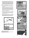
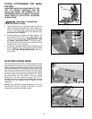
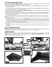
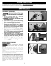
3. Place the crown moulding on the table with the CEILING EDGE (see inset for example) of the moulding against the
fence, and make the cut, as shown in Fig. 37.
NOTE: The piece of crown moulding used for the outside corner will always be on the right hand side of the blade, as
shown at (A) Fig. 37. The piece of crown moulding used for the inside corner will always be on the left hand side of
the blade, as shown at (B) Fig. 37.
4. To make the matching halves of the inside and outside corners, rotate the table to the 31.62° left miter position.
NOTE: A positive stop is provided to find this angle quickly. The saw blade is already tilted to the 33.86° bevel position
from the previous cut.
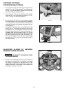
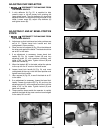
5. Place the crown moulding on the table with the WALL EDGE (see inset for example) of the crown moulding against
the fence and make the cut. Again, the piece of crown moulding used for the outside corner will always be on the
right side of the blade, as shown at (C) Fig. 38. The piece of crown moulding used for the inside corner will always
be on the left side of the blade, as shown at (D) Fig. 38.
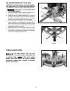
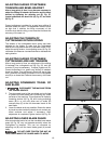
6. Fig. 39 illustrates the two outside corner pieces; (A) being the piece cut at (A) Fig. 37 and (C) being the piece cut at
(C) Fig. 38.
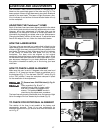
7. Fig. 40 illustrates the two inside corner pieces; (B) being the piece cut at (B) Fig. 37, and (D) being the piece cut at
(D) Fig. 38.
45-45 CROWN MOULDING
NOTE: If you are cutting crown moulding that is 45°-45°, follow the same procedure above, with the exception that the
bevel position will always be at 30° and the miter position will be 35-1/4° to the right or left.
OTHER ANGLES
NOTE: The above instructions are assuming the angle between the walls is 90°. If you need help cutting crown
moulding set at angles other than 90°, see the instruction sheet “CUTTING CROWN MOULDING” on the Delta
Machinery web site at www.deltamachinery.com.
D
C
B
A
C
A
B
D
WALL
EDGE
CEILING
EDGE
Fig. 38
Fig. 37
Fig. 39
Fig. 40