


12
NOTE: The belt tension is pre-set at the factory and
should only require adjusting if the belt stretches over
time or is replaced.
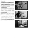
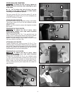
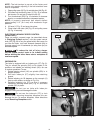
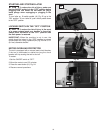
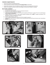
1. Open pulley cover (X) Fig. 14 and side door (AA) Fig. 16.
2. Pull down belt tensioning lever (Y) Fig. 15 to release
belt tension. Do not lock it below the tab (Z).
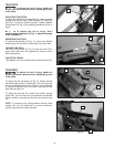
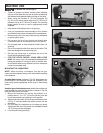
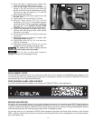
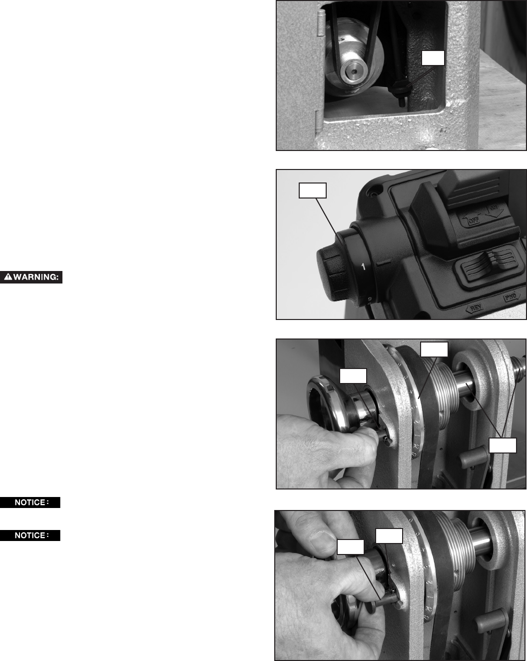
3. Turn thumbwheel (DD) Fig. 19 clockwise to increase
tension, or counterclockwise to decrease tension.
NOTE: A properly tensioned belt should deflect
approximately 1/4" (6.4 mm) with moderate finger
pressure.
4. Lift lever (Y) Fig. 15 and snap into place.
5. Close lower side door (AA) Fig. 16 and pulley cover
(X) Fig. 14 securely.
ELECTRONIC VARIABLE SPEED CONTROL
(46-460 ONLY)
Once you select a speed range (as described above
in Changing Pulleys section), use the speed control
knob (EE) Fig. 20 to vary the speed within that range. As
you face the lathe, turn knob forwards (towards you) to
increase speed, turn it backwards (or away from you) to
decrease speed.
To reduce the risk of injury, always
set the speed control knob to its lowest setting
before starting the lathe. Never start a workpiece at
maximum speed.
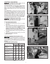
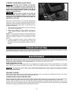
INDEXING PIN
The lathe is equipped with an indexing pin (FF) Fig. 21.
The pin allows the spindle (GG) to be locked in 24
positions—as labeled on indexing wheel (HH)—for use
in various operations. To use:
1. Rotate idexing wheel (HH) so spindle (GG) is in
desired location.
2. Pull back index pin (FF) slightly from retaining
groove.
3. Rotate indexing pin 90 degrees so the crosspin (II)
lines up with recess, as shown in Fig. 21a.
4. Release indexing pin (FF) so that it engages
numbered indexing wheel (HH) Fig. 21 and locks
spindle (GG) in place.
Do not turn on lathe with index pin
engaged. Doing so could damage the lathe.
Do not use the index pin (FF) to lock
spindle when removing faceplate because this can
damage the pin. To remove faceplate, follow directions
under Removing Faceplate section.
Fig. 20
Fig. 21
Fig. 21a
DD
EE
FF
HH
GG
FF
II
Fig. 19