12
Fig. 24
A
B
Fig. 23
A
E
C
D
Fig. 25
F
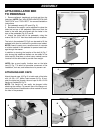
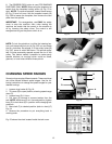
6. The REVERSE (REV) button is used FOR SANDING
PURPOSES ONLY. NOTE: When using the faceplate, be
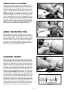
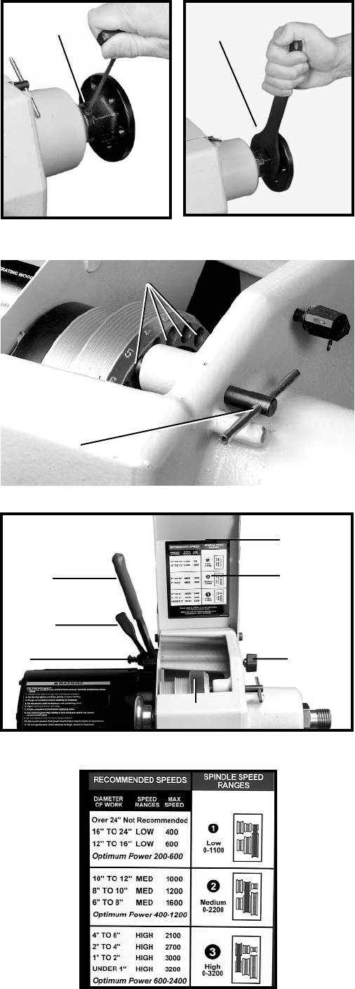
certain that the faceplate locking screw (A) Fig. 23 is
tight. NOTE: To remove faceplate, loosen the set screw
(A) Fig. 23 two full turns. Use the supplied wrench (B)
Fig. 23B to loosen the faceplate, then remove the face
plate from the spindle.
IMPORTANT: For emergencies, use ONLY the safety
cover to stop the machine. Also, when leaving the
machine, be certain that the power to the machine is
off by lowering the safety cover. The control is still
energized as long as the power switch is on.
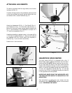
NOTE: To lock the spindle or to utilize the indexing fea-
ture, pull the spindle lock pin (A) Fig. 23C out and rotate
the pin clockwise. Re-engage it in the pulley holes (B)
Fig. 23C, some of which are shown. The spindle pulley
has 24 holes accurately spaced around the rim of the
pulley. This feature makes it possible to make evenly
spaced divisions on turnings which could be fluted,
grooved, or have holes drilled at these points.
CHANGING SPEED RANGES
Some turnings require different speeds. These machines
can utilize several different speed ranges. Use the fol-
lowing instructions to change the speed ranges for your
desired turnings.
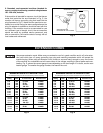
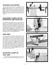
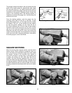
1. Loosen wing knobs (A) Fig. 24.
2. Tilt cover (B) to open position, showing speed range
chart (C).
3. Loosen lever (D) 1/4 turn.
4. Pull lever (E) forward to remove tension from the
belt. NOTE: While lever (E) is in forward position, tighten
lever (D) to hold lever (E) in position while changing belt
positions.
5. Move belt (F) to desired position (refer to chart) (C)
Fig. 24.
6. Reverse the procedure to put everything back in
working order.
Fig. 25 shows the chart located inside the belt cover.
A
B
Fig. 23B
Fig. 23C
A
B


