


6
ASSEMBLY
WARNING: FOR YOUR OWN SAFETY, DO NOT CONNECT THE MACHINE TO THE POWER SOURCE UNTIL
THE MACHINE IS COMPLETELY ASSEMBLED AND YOU READ AND UNDERSTAND THE ENTIRE INSTRUCTION
MANUAL.
Fig. 5
Fig. 6
Fig. 7
Fig. 8
T
R
I
J
I
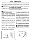
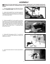
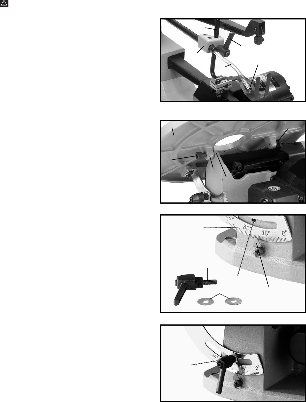
1. Remove the blade from the upper blade holder. (See the
section “CHANGING BLADES”, begin with instruction #3).
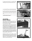
2. Loosen lock handle (K) Fig. 5, and insert long end of
holddown assembly (D) up through hole in bracket (L).
Then tighten lock handle (K). Connect end of air hose (M)
to air nozzle (N) as shown.
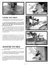
3. Position table (B) Fig. 6, on the machine, as shown,
making sure pin (O) in rear table casting is engaged with
hole in base casting. Insert pivot bolt (E) through hole in
table casting (P) and thread into base (Q) using the 6mm
wrench. Thread M6 hex nut on end of pivot bolt (E).
Make sure the tilt scale (R) Fig. 7, is positioned inside
pointer (S) as shown.
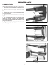
4. Position M6.4 flat washers (J) Fig. 7, on inside and
outside of tilt scale (R) and thread end of table lock
handle (I) into hole (T).
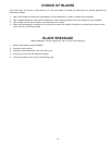
5. Figure 8 illustrates table lock handle (I) assembled to
machine.
S
D
L
M
K
N
B
E
P
Q
O