


Chapter 5 Parameters|VFD-S Series
5-76 Revision August 2006, SE08, SW V2.61
When this parameter is set to gain =1, PID output is Derivative time. At this time, error value –
error value of the preceding item= additional respond speed and it is easy to have over
compensation situation.
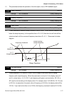
A-05 Upper Bound for Integral Control Unit: 1
Settings d0 to d100% Factory Setting: d100
This parameter determines the Upper Bound for Integral Control while operating in the PID
feedback loop. (Limit = 1-00×A-05 %). During a fast Integration response, it is possible for
the frequency to spike beyond a reasonable point. This parameter will limit this frequency
spike.
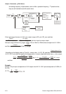
A-06
Primary Delay Filter Time
Unit: 2 msec
Settings d0 to d999 Factory Setting: d0
Primary Delay Filter Time will slow down oscillation of the system.
A setting of d0 disables this function.
A-07
PID Output Frequency Limit
Unit: 1
Settings d0 to d110% Factory Setting: d100
This parameter determines the limit of the PID output frequency. If this parameter is set to
110%, then the maximum output frequency while in the PID operation will be (110% x Pr.01-
00) 66Hz.
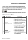
A-08
Feedback Signal Detection Time
Unit: 0.1
Settings d0.0 to d650 seconds Factory Setting: d0.0
This parameter defines the detection time for the loss of a feedback analog signal. The drive
will follow the operating procedure programmed in Pr.A-09 if the feedback signal is lost for
more than the time set in Pr. A-08.
A setting of 0.0 disables this function.
A-09 Treatment of the Erroneous Feedback Signals
Factory Setting: d0
Settings d0 Warning and RAMP to stop
d1 Warning and COAST to stop