


2
Chapter 3 Components and Functions
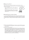
Place the CU on a flat, horizontal plane. Do not install the CU on a wall or in a
vertical position.
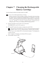
LED indicators
DATA (Communications LED, green)
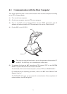
Lights when the BHT is communicating
with the host computer.
POWER (Power LED, green)
Lights when the power is applied to
the CU-7011.
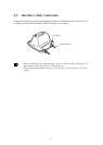
Optical interface port
Used to exchange data optically
with the BHT.
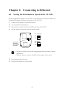
Ethernet interface port (10Base-T)
Used to connect to an Ethernet.
Power inlet connector
Plug the AC adapter into this connector.
BHT charge terminals
Do not stain these
terminals; failure to
protect the terminals
may result in decreased
charging efficiency.)
CU-7011