


6 ENG
DESCRIPTION OF OPERATIONDESCRIPTION OF OPERATION
DESCRIPTION OF OPERATIONDESCRIPTION OF OPERATION
DESCRIPTION OF OPERATION
automatically release compressed air from the compressor
head and the outlet tube when the air compressor reaches
“cut-out” pressure or is shut off. If the air is not released, the
motor will try to start, but will be unable to. The pressure
release valve allows the motor to restart freely. When the
motor stops running, air will be heard escaping from this valve
for a few seconds. No air should be heard leaking when the
motor is running, or continuous leaking after unit reaches
cut-out pressure.
Pressure Switch:Pressure Switch:
Pressure Switch:Pressure Switch:
Pressure Switch: The pressure switch automatically starts
the motor when the air tank pressure drops below the factory
set “cut-in” pressure. It stops the motor when the air tank
pressure reaches the factory set “cut-out” pressure.
Safety Valve:Safety Valve:
Safety Valve:Safety Valve:
Safety Valve: If the pressure switch does not shut off the air
compressor at its cut-out pressure setting, the safety valve
will protect against high pressure by “popping out” at its
factory set pressure (slightly higher than the pressure switch
cut-out setting).
Outlet Pressure Gauge:Outlet Pressure Gauge:
Outlet Pressure Gauge:Outlet Pressure Gauge:
Outlet Pressure Gauge: The outlet pressure gauge indi-
cates the air pressure available at the outlet side of the
regulator. This pressure is controlled by the regulator and is
always less or equal to the tank pressure.
Tank Pressure Gauge: Tank Pressure Gauge:
Tank Pressure Gauge: Tank Pressure Gauge:
Tank Pressure Gauge: The tank pressure gauge indicates
the reserve air pressure in the tank.
Cooling System: This compressor contains an advanced
design cooling system. At the heart of this cooling system is
an engineered fan. It is perfectly normal for this fan to blow
air through the vent holes in large amounts. You know that the
cooling system is working when air is being expelled.
Drain Valve:Drain Valve:
Drain Valve:Drain Valve:
Drain Valve: The drain valve is located at the base of the air
tank and is used to drain condensation at the end of each use.
Motor Thermal Overload Protector:Motor Thermal Overload Protector:
Motor Thermal Overload Protector:Motor Thermal Overload Protector:
Motor Thermal Overload Protector: The electric motor
has an automatic thermal overload protector. If the motor
overheats for any reason, the thermal overload protector will
shut off the motor. The motor must be allowed to cool before
restarting.
ON/AUTO - OFF Switch:ON/AUTO - OFF Switch:
ON/AUTO - OFF Switch:ON/AUTO - OFF Switch:
ON/AUTO - OFF Switch: Turn this switch ON to provide
automatic power to the pressure switch and OFF to remove
power at the end of each use.
Air Intake Filter:Air Intake Filter:
Air Intake Filter:Air Intake Filter:
Air Intake Filter: This filter is designed to clean air coming
into the pump. This filter must always be clean and ventila-
tion openings free from obstructions. See "Maintenance".
Air Compressor Pump:Air Compressor Pump:
Air Compressor Pump:Air Compressor Pump:
Air Compressor Pump: To compress air, the piston moves
up and down in the cylinder. On the downstroke, air is drawn
in through the air intake valves. The exhaust valve remains
closed. On the upstroke of the piston, air is compressed. The
intake valves close and compressed air is forced out through
the exhaust valve, into the outlet tube, through the check
valve and into the air tank. Working air is not available until
the compressor has raised the air tank pressure above that
required at the air outlet.
Check Valve: Check Valve:
Check Valve: Check Valve:
Check Valve: When the air compressor is operating, the
check valve is “open”, allowing compressed air to enter the
air tank. When the air compressor reaches “cut-out” pres-
sure, the check valve “closes”, allowing air pressure to
remain inside the air tank.
Pressure Release Valve:Pressure Release Valve:
Pressure Release Valve:Pressure Release Valve:
Pressure Release Valve: The pressure release valve
located on the side of the pressure switch, is designed to
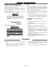
It may be necessary to brace or support one
side of the outfit when removing the shipping
boards because the air compressor will have a
tendency to tip.
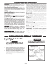
1. Remove all packaging such that only the compressor on
the pallet remains. Remove and discard the (4) screws
and washers that hold the compressor to the pallet.
2. Stationary air compressors must be bolted to the floor.
Bolting holes are provided in the base feet. Mount the air
compressor on a solid, level foundation. Support com-
pressor weight evenly on all four feet. Solid shims may be
used if necessary.
EXCESSIVE VIBRATION CAN WEAKEN THE
AIR TANK AND CAUSE AN EXPLOSION. THE
COMPRESSOR MUST BE PROPERLY MOUNTED
AS ILLUSTRATED BELOW.
Removal of Shipping Boards and InstallationRemoval of Shipping Boards and Installation
Removal of Shipping Boards and InstallationRemoval of Shipping Boards and Installation
Removal of Shipping Boards and Installation
for (Stationary) Unitsfor (Stationary) Units
for (Stationary) Unitsfor (Stationary) Units
for (Stationary) Units
INSTINST
INSTINST
INST
ALLAALLA
ALLAALLA
ALLA
TION AND BREAKTION AND BREAK
TION AND BREAKTION AND BREAK
TION AND BREAK
-IN PROCEDURES-IN PROCEDURES
-IN PROCEDURES-IN PROCEDURES
-IN PROCEDURES