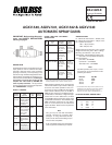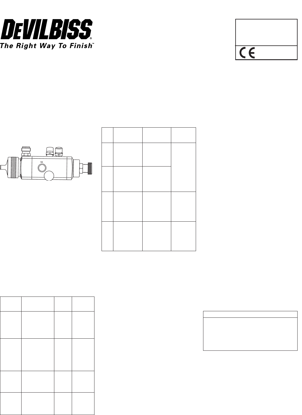
AGXV-540, AGXV-541, AGXV-542 & AGXV-543
AUTOMATIC SPRAY GUNS
SERVICE BULLETIN
SB-2-628-K
Replaces SB-2-628-J
Repair Kit KK-4992-1
IMPORTANT: Before using this equip-
ment, read SAFETY PRECAUTIONS
starting on page 2.
DESCRIPTION
The AGXV high volume, low pressure spray gun
(spray pistol) is used on automatic and semi-
automatic machines where mass production
spraying is necessary, or hand spraying is not
accurate enough. Models and application infor-
mation follows. All models are designed to pro-
vide maximum transfer efficiency by limiting air
cap pressure to 10 psi (0.7 bar) (in the U.S., this
complies with rules issued by SCAQMD and
other air quality authorities). Air cap pressure
can be measured with an optional air cap test kit.
See "ACCESSORIES" on Page 8.
CHART 1 MODELS
Model No. HVLP Fluid
(Available Typical Air Cap Tip/Needle
Tip Sizes) Applications Used Construction
AGXV-540 Most common 28 or 33A 400 Gr. S/S
(E, FF, FX) finishing materials
including some
waterborne and
chlorinated.
AGXV-541 High solids (low 46MP or 400 Gr. S/S
(D, E, FF, VOC's) coatings 83MP
FX) which are difficult
to atomize with
HVLP, or high
flow rates.
AGXV-542 Waterbornes and 28 or 33A 303 Gr. S/S,
(FF, FX) other corrosive Poly.
materials (below
7pH)
AGXV-543 Same as AGXV- 46MP 303 Gr. S/S,
(FF, FX) 541 except for Poly.
more corrosive ma-
terials (below 7pH)
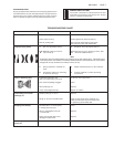
CHART 2 AIR CAPS – PATTERNS –
APPLICATION
Air Complete *Typical
Cap Air Cap Pattern Size Typical
No. No. and Shape Application
28 JGHV-101-28 11" (280 mm)
long, straight Most com-
sided, similar to mon finishing
704 air cap. materials, up
to 12 oz./min.
33A JGHV-101-33A 9" (229 mm) (360 cc)
long, tapered
ends, similar to
30 air cap.
46MP JGHV-101-46MP 11" (280 mm) Low VOC
long, straight materials, 12
sided, similar to to 16 oz./min.
704 air cap. (360 to
480 cc)
83MP JGHV-101-83MP 13" (330 mm) Low VOC
long, straight materials,
sided similar to 17 oz./min.
765 air cap. (510 cc) and
above.
* Actual pattern length dependent upon fluid tip (nozzle) ID,
coating material flow rate, air pressure and fan pressure.
Most finishing materials can be atomized with
either the 28 or 33A air caps. The 28 or 33A caps
should be used where possible as they con-
sume less air volume (CFM) and have slightly
better transfer efficiency than the 46 MP or
83MP air caps. However, more difficult to atom-
ize materials (i.e. low VOC's) or high flow appli-
cations over 12 oz./min. (360 cc/min.), are ideal
for the 46 MP maximum performer air cap, fluid
tip and baffle combination. Also available is the
83MP (maximum performer) for even higher
flows 17 oz./min. (510 cc/min.) and above and
higher viscosities. Refer to the air cap chart for
more information.
Note
This gun may be used with chlorinated
solvents. Aluminum is not used in fluid
passages. If using chlorinated solvents,
make sure all other fluid handling compo-
nents are also compatible.
A list of materials used in the construction
of this equipment is available upon request.
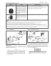
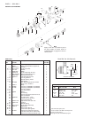
SPECIFICATIONS
P1 – Maximum Inlet Pressure – 100 PSI (7 bar)
P2 – Maximum Fluid Pressure – 100 psi (7 bar)
P3 – Cylinder Air Pressure
– Min. **50 psi (3.5 bar)
– Max. 100 psi (7 bar)
Weight without mounting stud – 26 oz. (738 g)
Weight with mounting stud – 30.5 oz. (865 g)
Mounting stud diameter – 3/4" (19 mm)
Wetted Parts – 300 and 400 S/S, Teflon, Poly.
(See Chart 2 for tip/needle information)
Hose Connections –
Fluid Inlet – 3/8" NPS(M)
Cylinder Air – 1/4" NPS(M)
Atomization Air – 1/4" NPS(M)
Note
For HVLP operation (max. 10 psi, - 0.7 bar
cap pressure), do not exceed the air inlet
pressure given below.
PSI (bar) Cap No.
57 (4) 83MP
50 (3.4) 46MP
45 (3.1) 33A
38 (2.6) 28
**For installations where 50 psi (3.4 bar) cylinder air is not
available, the inner (red) piston spring can be removed
which lowers the minimum cylinder air to approxi-
mately 37 psi (2.5 bar). Refer to "OPERATION", Pg. 4
FLUID TIP (NOZZLE) ORIFICE SIZES
Inch mm
D .086" 2.2
E .070" 1.8
FF .055" 1.4
FX .042" 1.1
G 0.028 .7