


PAGE 4 SB-2-628-K
OPERATION
1. Mix, prepare and strain the material to be sprayed according to the
paint manufacturer’s instructions. Use a lint free mesh to strain the
material.
2. Turn on the cylinder air at source of supply. Supply air should be a
minimum of 50 PSI (3.5 bar). For consistant operation the pressure
should be regulated. If 50 psi (3.5 bar) cylinder air pressure is not
available, the red inner spring (31) can be removed. This allows a
minimum cylinder pressure of approximately 37 psi (2.6 bar).
Note
If the red inner spring (31) is removed, atomization pressure
should not exceed 70 psi (4.8 bar) (will result in gun not shutting
off).
3. Turn the needle adjustment knob (25) counterclockwise several turns.
With the cylinder air on, turn the adjustment knob (25) clockwise until
it contacts piston (19) (for maximum fluid flow). Back knob out 1/2 turn.
Note
Due to close part tolerances, actuate the gun on and off 7 or 8
times to "break-in" the packings. Do this with the material
supply off.
4. Adjust the atomization air pressure to 50 PSI (3.5 bars) or less. Aways
attempt to keep the pressure as low as possible to minimize overspray.
The fluid pressure should be between 10 to 15 PSI (0.7 to 1.0 bar).
5. Open the hand valve and/or trip the automatic valve if installed in the
system and observe the spray pattern. Adjust the air and fluid
pressures until the desired pattern is obtained. Control the fluid
pressure at the source of supply. If the desired regulation is not
practical at this point, restrict the flow by turning the adjustment knob
(25) clockwise.
Back Pressure – 46MP and 83MP "Maximum Performer"
Due to the unique cone shape of the MP fluid tips (nozzle), a slight back
pressure is created against the fluid column. This will reduce the amount
of fluid output. To compensate, increase the fluid regulator pressure
slightly if necessary. With 10 PSI (0.7 bar) cap pressure, back pressures are
approximately 3.5 PSI (0.24 bar) with the 46MP and 2.0 PSI (0.14 bar) with
the 83MP.
6. The width of the spray pattern is controlled by the adjusting valve (23)
marked “FAN” . With the “FAN” valve screwed fully clockwise, the
spreader air will be closed off causing a round pattern. By gradually
opening this valve, the pattern changes to a fan spray. The width is
determined by the amount the valve is opened. Atomization air is
adjusted by regulating the supply air to the gun.
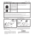
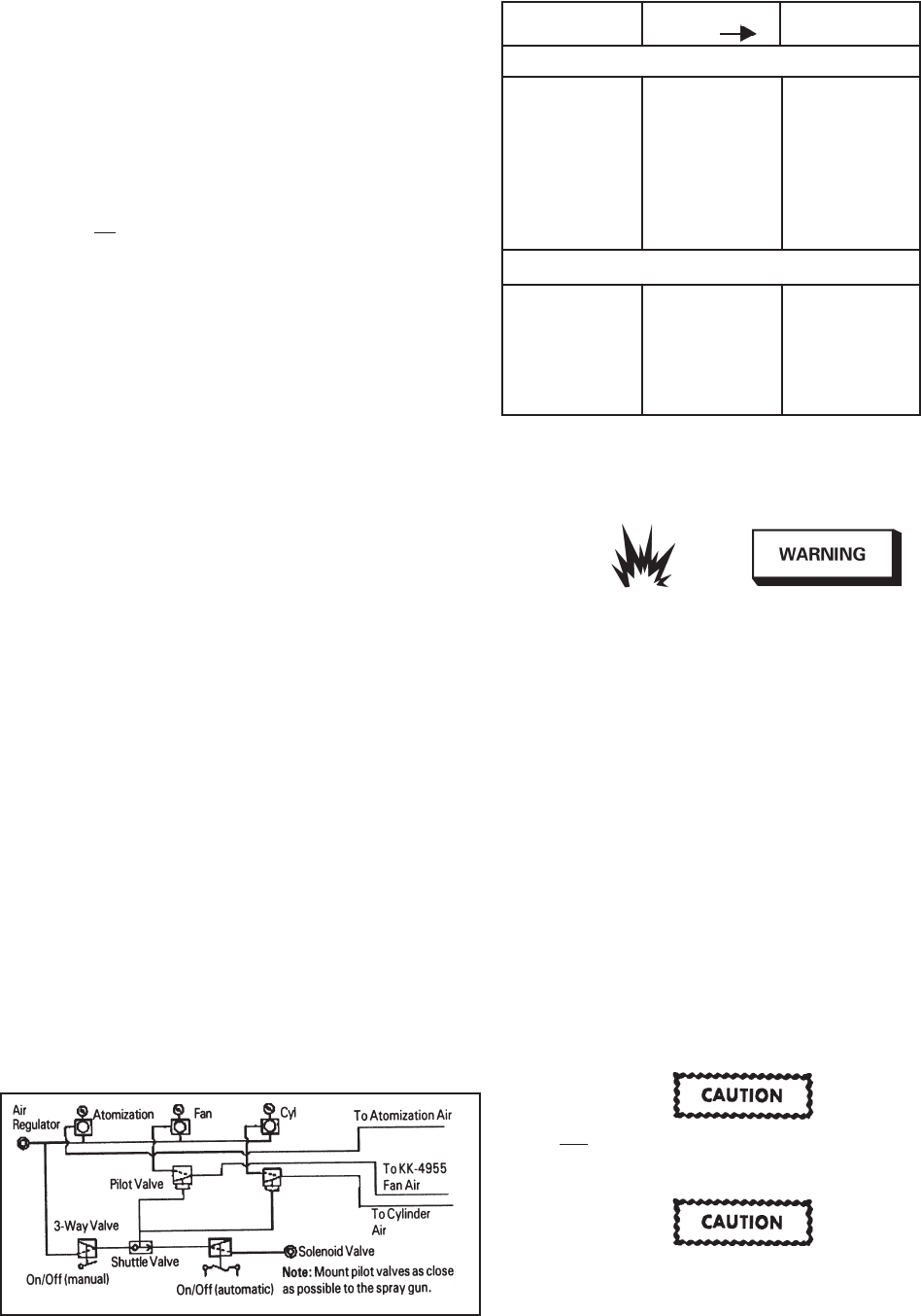
Adjustments to fan may be controlled remotely by using the optional
KK-4955 fan control adapter to replace the AGG-403 control valve (23).
A separate solenoid valve is required to control on/off function. See
Figure 2A.
7. Close the automatic valves and begin operation.
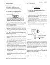
FIGURE 2A AIR CIRCUIT EXAMPLE WITH
OPTIONAL KK-4955 REMOTE FAN CONTROL
PREVENTIVE MAINTENANCE
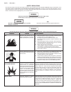
Risk of Injury. Equipment and fluid may be under pressure.
Pressure in the system must be relieved before beginning
the cleaning procedure and before replacing any parts.
Follow the procedures in the literature provided with the
system.
Cleaning
1. Relieve air pressure from the pressure feed tank. Carefully
follow the instructions in the bulletin sent with the tank.
2. Replace material in the container with a suitable solvent.
3. Repressurize the system.
4. Trigger the gun and repeat the procedure until the gun and hose
are thoroughly clean (solvent is clean when it looks the same as
when you first opened solvent container). A SolventSaver™
type hose and gun cleaner which supplies a mixture of air and
solvent can be used to most effectiverly clean the gun and hose
internal passages. See "Accessories" on back page. Wipe the
exterior of the gun with a solvent dampened cloth.
5. If a recirculating system is used, it may be necessary to fit a shut
off valve in the return line to ensure the fluid tip and forward
portion of the sprayhead passage are properly cleaned when
flushed with solvent.
Do not totally submerge the gun in solvent. It is possible
to wash solids into the air operating sections of the gun
which could damage piston "O" ring seals.
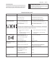
The air cap can be immersed in solvent for cleaning. If the
orifices are clogged, use a broom straw or toothpick to
remove the obstruction. Never use a steel wire or hard
instrument. This will damage the air cap and result in a
distorted spray pattern.
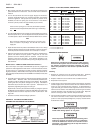
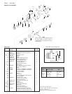
If this No. on Tip Fluid Tip &
Tip Size ORDER Needle Set
400 Gr. Stainless Steel
In mm
E .070" 1.8 AV-2115-E AGX-4402-E
FF .055" 1.4 AV-2115-FF AGX-4402-FF
FX .042" 1.1 AV-2115-FX AGX-4402-FX
G .028" 0.8 AV-2115-G AGX-4402-G
FF .055" 1.4 AV-2120-FF AGX-4600-FF*
FX .042" 1.1 AV-2120-FX AGX-4600-FX*
D .086" 2.2 AV-2120-D AGX-4483-D**
E .070" 1.8 AV-2120-E AGX-4483-E**
303 Gr. Stainless Steel, U.H.M.W. Poly.
E .070" 1.8 AV-4915-E AGX-4300-E
FF .055" 1.4 AV-4915-FF AGX-4300-FF
FX .042" 1.1 AV-4915-FX AGX-4300-FX
FF .055" 1.4 AV-4920-FF AGX-4613-FF*
FX .042" 1.1 AV-4920-FX AGX-4613-FX*
E .070" 1.8 AV-4920-E AGX-4613-E
D .086" 2.2 AV-4920-D AGX-4613-D
* For use with 46MP air cap.
** For use with 83MP air cap.
CHART 3 FLUID TIPS (NOZZLE) AND NEEDLES