


9- ENG
D23757
ASSEMBLY (does not apply to all units)
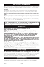
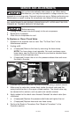
Assembly for “Pancake” units
1. Carefully place unit on side opposite of controls.
2. Using a 3/8 inch socket or nut driver
remove the screws attaching the unit to the
shipping pallet.
NOTE: These screws will be used to install the
rubber feet.
3. Attach the four rubber feet to the unit’s legs
using the four screws removed in step 2.
NOTE: Flat side of rubber feet goes against unit legs.
Leg
Rubber
Foot
Screw
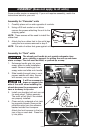
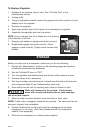
Assembly for “Tank” units
The wheels and handle do not provide adequate clear-
ance, stability or support for pulling the unit up and down
stairs or steps. The unit must be lifted, or pushed up a ramp.
1. Submerge handle grip into warm
soapy water to make installation
easier. Remove handle grip from
soapy water and slide onto handle.
2. Slide handle through holes in com-
pressor saddle onto tabs. Secure
with screws, one on each side.
It will be necessary to
brace or support one
side of the outfit when installing the
wheels because the compressor will
have a tendency to tip over.
3. Install one shoulder bolt and one nut
for each wheel. Tighten securely.
The outfit will sit level if the wheels
are properly installed.
4. Clean and dry underside of air tank
leg opposite wheels. Remove the
protective strip from the adhesive
backed molded foot bumpers.
Attach the foot bumpers to the bot-
tom of leg on each end. Press firm-
ly into place.
Wheel
Shoulder Bolt
Nut
Handle
Screw
Compressor Saddle
Tab
Molded Foot Bumpers
Some models require no assembly. If your unit requires assembly, match the
instructions below to your unit.